Get OW4 POINT I/O 4 POINT DIGITAL OUTPU at wholesale prices at Westburne – your electrical distributor. Join Now!. OW2 and OW4, Series C).
Description Wiring Base Assembly consists of item 1) mounting base, MB and item 7) removable terminal The examples and diagrams in this manual are included solely for illustrative purposes. Catalog numbers OW2, OW4, OW4K, Series C. Catalog numbers with the suffix ..
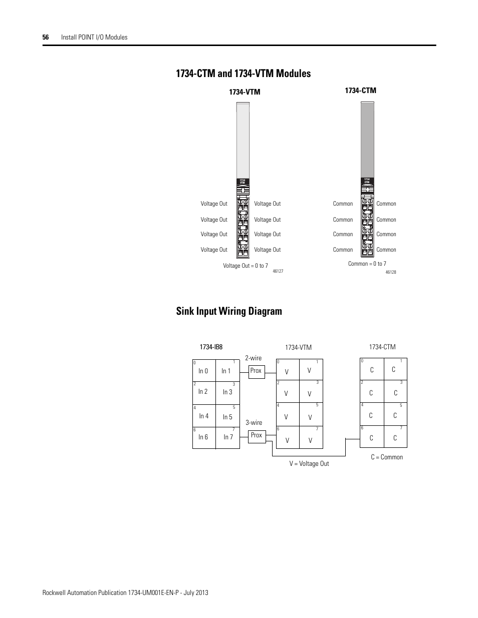
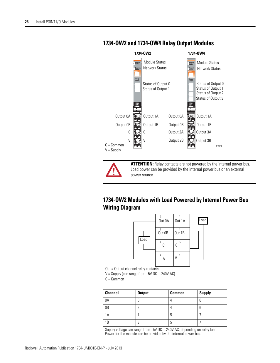
or spring clamp (RTBS). Module wiring diagram. OW2 and OW4, Series C).
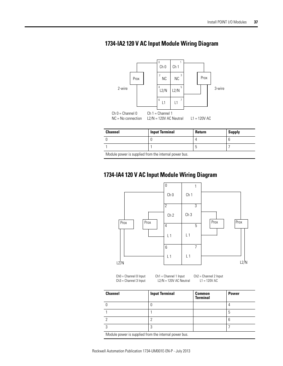
Description Wiring Base Assembly consists of item 1) mounting base, MB and item 7) removable terminal The examples and diagrams in this manual are included solely for illustrative purposes. 26 Install POINT I/O Modules.
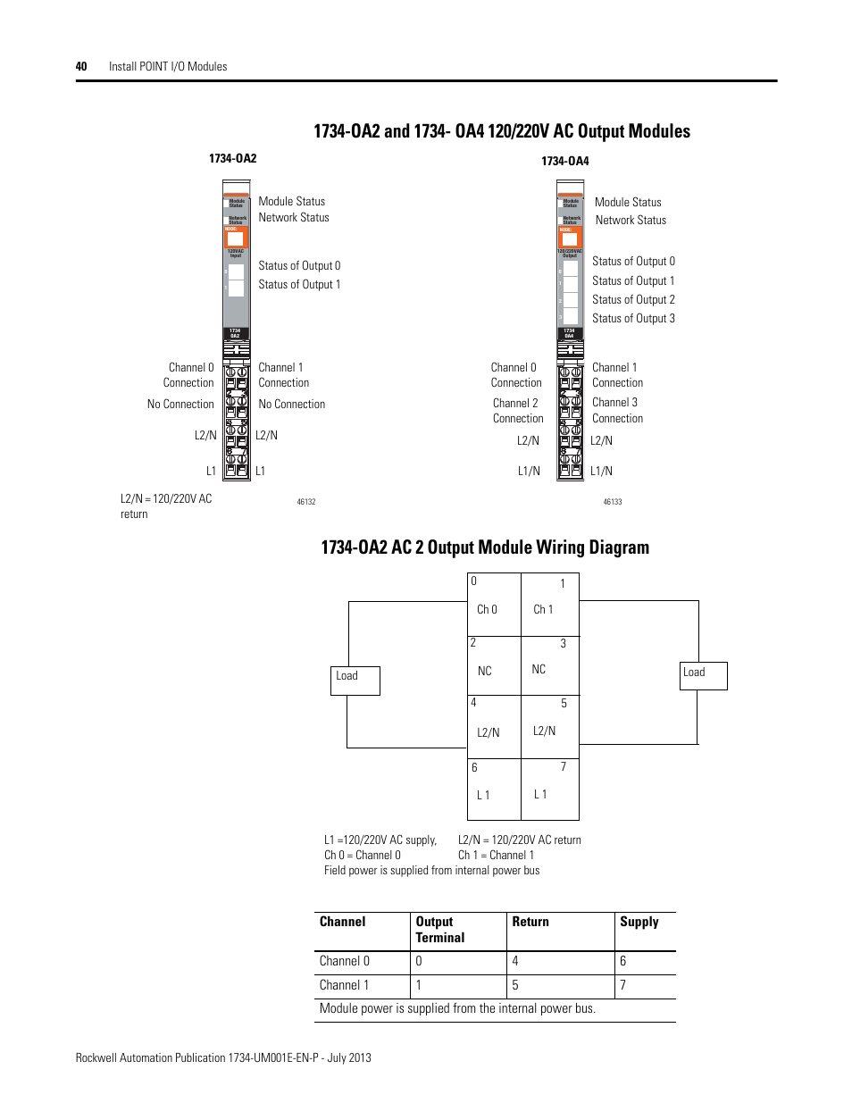
OW2 and OW4 Relay Output Modules. OW2 Modules with Load Powered by Internal Power Bus Wiring Diagram.POINT I/O 4 Channel Analog Current Output Module Module locking mechanism Module wiring diagram DIN rail locking screw (orange) Slide-in writable label Insertable I/O module Handle Mechanical keying (orange) Interlocking side pieces TOP or TOPS one-piece terminal base with screw or spring clamp Install the Mounting Base To.
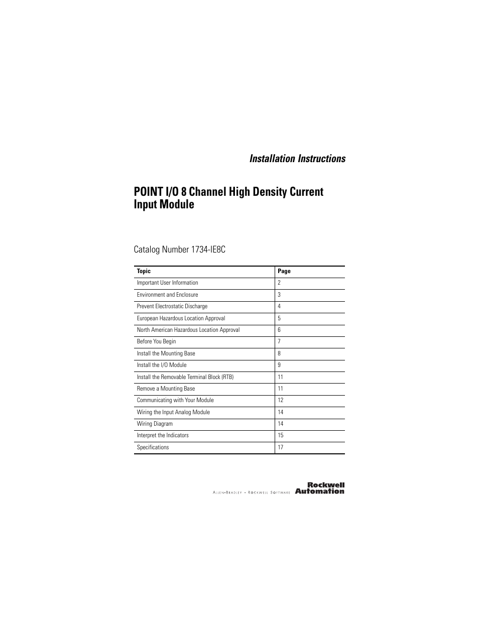
– wiring diagram IE8C. Abstract: OW4 wiring TB MB ow4 wiring diagram IB8s ie8c wiring connections OW4+wiring OW4 EP24DC Text: Installation Instructions POINT I/O 2 and 4 Relay Output Modules Catalog numbers OW2, OW4 . Ib8s Wiring Diagram ~ welcome to our site, this is images about ib8s wiring diagram posted by Ella Brouillard in category on Nov 24, You can also find other images like wiring diagram, parts diagram, replacement parts, electrical diagram, repair manuals, engine diagram, engine scheme, wiring harness, fuse box, vacuum diagram, timing belt, timing chain, brakes diagram.
Provides installation information about TB and TBS assemblies POINT I/O Wiring Base Assembly Installation Instructions, publication IN Provides installation information about TB3 and TB3S publication IN Provides installation information about OW2 and OW4 modules. (Cat.
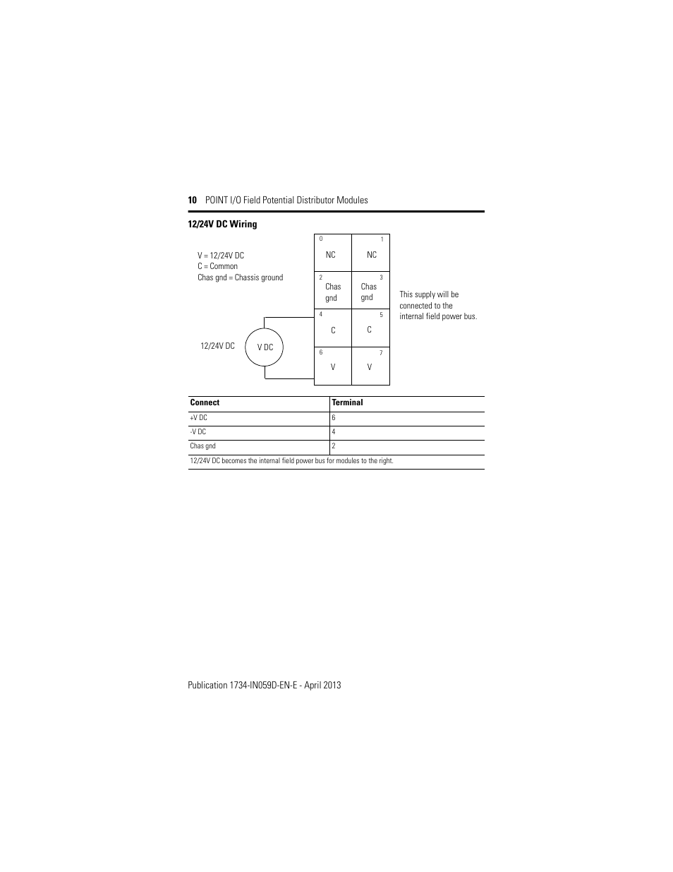
No. OW2 and OW4, Series C) Description Description 1 Mounting Base1 6 RTB Removal Handle 2 Mechanical Keying (orange) 7 Removable Terminal Block (RTB)1 3 Module Wiring Diagram 8 DIN Rail Locking Screw (orange) 4 Module Locking Mechanism 9 Slide-in Writable Label 5 Insertable I/O Module 10 Interlocking Side Pieces.PLC Hardware – Allen Bradley OW4 Series C, Used in a PLCH PackagingIb8s Wiring Diagram – schematron.org
