Allen-bradley OW16 Pdf User Manuals.
View online or download Allen- bradley OW16 Installation Instructions Manual. IB8.
Input. 8.
Current Sinking DC Input. 24V dc.
IB Input .. Related Publications: Detailed wiring diagrams for input modules and. Do we have a wiring diagram showing how field devices are wired to a OW16 with IFM20F-F-2 or RIFM20F-F-2 IFM module?
See the file. Manual.
Description; Buy; Works with; Related models; More like this; Manuals The Allen-Bradley SLC Model Output Module receives and stores. The examples and diagrams in this manual are included solely for illustrative purposes.
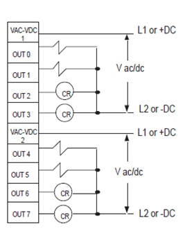
OW8, OW16, OX8, IO4, IO8, IO12 .Aotewell Ltd schematron.org Industry Automation SLC Digital I/O Modules Relay Contact Output Modules Wiring Diagrams OW4, OW8, OW16 OW4 OW8 Relay Output Relay Output L1 or +DC VAC-VDC L1 or +DC VAC-VDC OUT 0 OUT 0 V AC/DC V AC/DC. Publication 2 Discrete Input and Output Modules Discrete I/O Module Summary ID Code Voltage Category Catalog Number Input/Output I/O Points Module Description Page.
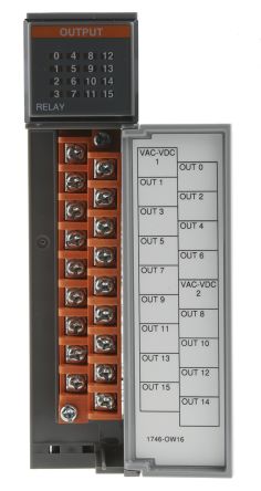
– Wiring Diagram for OW16 with IFM20F-F-2 or RIFM20F-F-2 IFM Module Access Level: Everyone Do we have a wiring diagram showing how field devices are wired to a OW16 with IFM20F-F-2 or RIFM20F-F-2 IFM module? Ib16 Wiring Diagram Wiring Wiring Diagrams Instructions Sample.
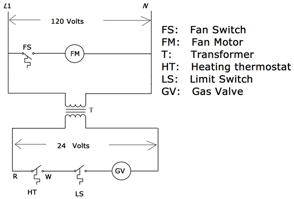
Find more here images of ow16 wiring diagram. See also ow16 wiring diagram Images below: What’s Wiring Diagram. A wiring diagram is a type of schematic which uses abstract pictorial symbols to show all the interconnections of components inside a system.
OW16, OX8 Combination Input/Output Catalog Numbers IO4 Prevent Electrostatic Discharge 4 Install and Remove the Module 5 Octal Label Kit Installation (for PLC processors only) 6 Wiring Diagrams 17 Apply the Octal Filter Label 6 Apply the Octal Door Label 6 The examples and diagrams in this manual are included solely for.Rockwell AutomationOw16 Wiring Diagram Sample | Wiring Collection