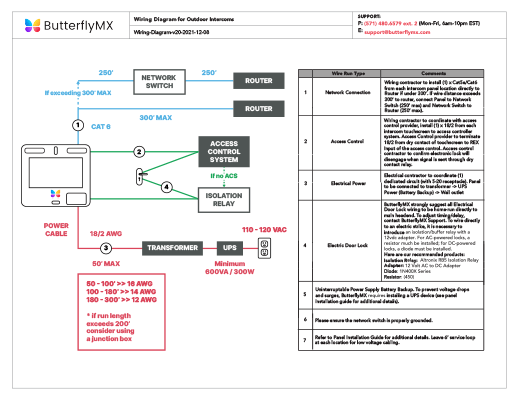
Rockwell Automation Lxxxx MicroLogix Programmable Controllers diagrams.
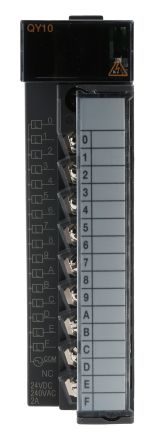
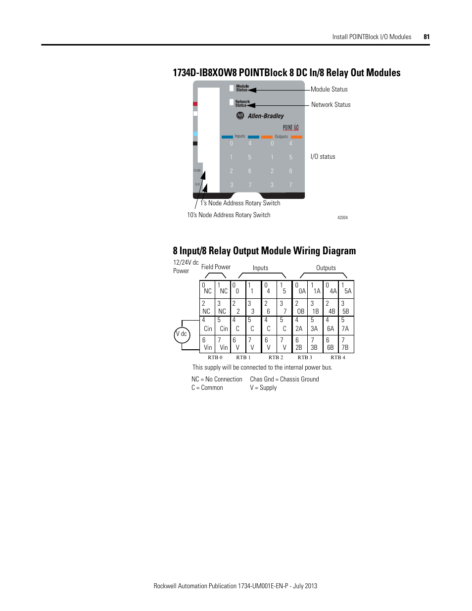
Discrete Wiring Diagrams. Figure IA8 Wiring Diagram. Allen-Bradley I/O Modules Wiring Diagrams Important User Information Solid O/12 through O/15 I/O on MicroLogix Controllers IA8 L1.
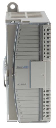
Allen-Bradley OW8 Module, Expansion, 8 Normally Open Relay, 5. Zoom.
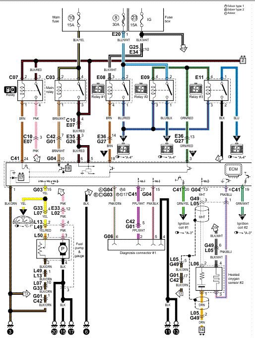
Mfr Number: OW8. Rexel Part Number: UPC: Allen-Bradley I/O Modules Wiring Diagrams Important User Information Solid O/12 through O/15 I/O on MicroLogix Controllers IA8 L1. Wire Your Controller Chapter 3 Figure 23 – OV32T Wiring Diagram Figure 24 – OW8 Wiring Diagram L1 VAC1 + VAC-VDC 1 OUT 0 CR L1.Installation & Field Wiring Guidelines Installation and Safety Guidelines 2–2 Installation & Field Wiring Guidelines DL High Speed Counter Interface Manual, 2nd Ed, Rev.
A How to Install the Module The D2–CTRINT module must be installed in slot 0 next to the CPU. .
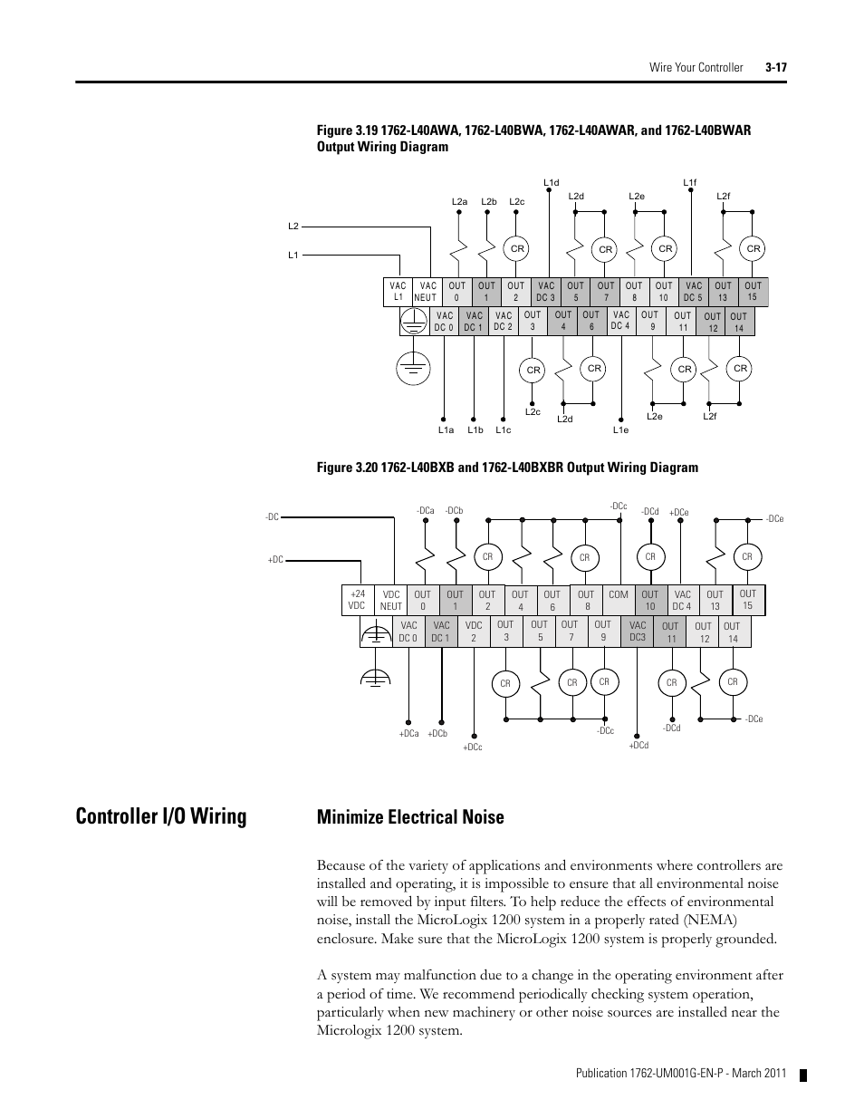
We would like to show you a description here but the site won’t allow us. MicroLogix IF2OF2 Analog Input/Output Module Catalog Number IF2OF2 Topic Page Important User Information 2 North American Hazardous Location Approval 4 Additional Resources 5 Overview 6 Module Description 7 Mount the Module 8 Field Wiring Connections 11 Wiring 13 Sensor/Transmitter Types 15 I/O Memory Mapping 17 Input Data File IA8 – In Stock | Allen Bradley PLC MicroLogix Service catalog: Buy, Sell, Repair.
IA8 V AC Input Module Installation Instructions, publication IN Installation guide for the IA8 Discrete Input Module. When wiring the terminal block, keep the finger-safe cover in place. 1.
Route the wire under the terminal pressure plate. You can use the stripped end of the wire or.A-B IA8 MICROLOGIX 8-PT VAC INPUTIA8 datasheet & applicatoin notes – Datasheet Archive
