View and Download Allen-Bradley MicroLogix IF4 installation instructions manual online.
Analog Input. MicroLogix IF4 Control Unit pdf manual.
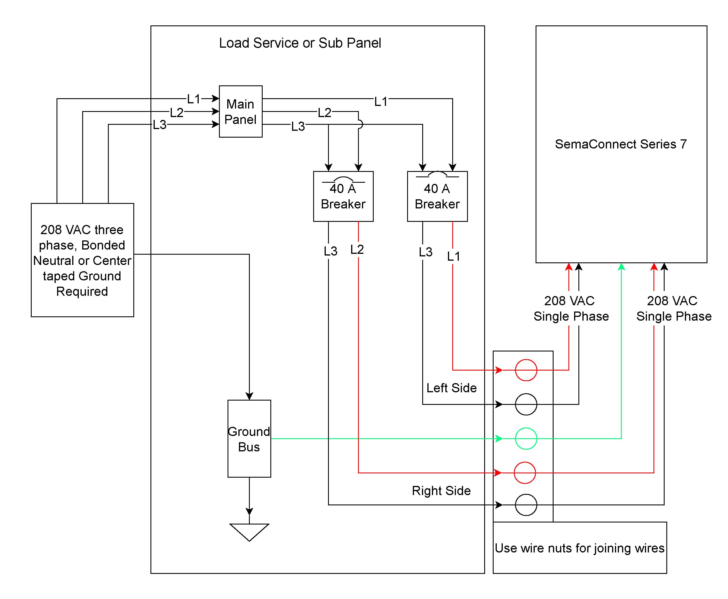
Wiring diagram is like so PLC Micrologix l40BWA In you offline program, does RSLogix list the IF4 as an available. Wiring and Grounding Guidelines, Allen-Bradley publication , for additional The IF4 module does not provide loop power for analog inputs .
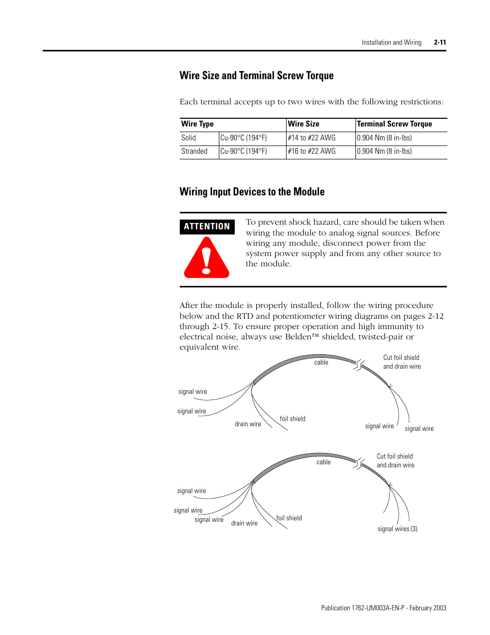
Rockwell Automation IF4 MicroLogix Analog Input Module User Manual • Basic input wiring to the if4 module • Rockwell Automation Equipment. The examples and diagrams in this manual are included solely for illustrative Analog.
IF4. 4-Channel Voltage/Current Analog Input Module. OF4.Page Field Wiring Connections.
MicroLogix IF4 Analog Input Module Field Wiring Connections Grounding the Module In solid-state control systems, grounding and wire routing helps limit the effects of noise due to electromagnetic interference (EMI). Compact™ IF4 (Series B or Later) Analog Input Module 9 Publication INA-EN-P Field Wiring Connections Grounding the Module This product is intended to be mounted to a well-grounded mounting surface such as a metal panel.
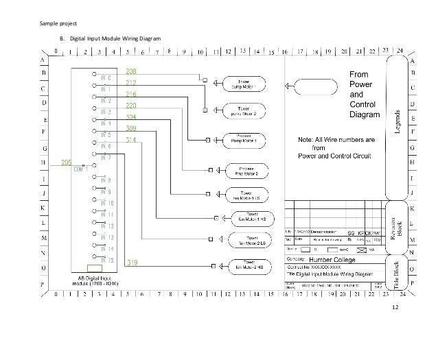
Additional grounding connections from the. IQ32T IQ32T in INA-EN-P PN IQ32 Micrologix terminal wiring diagram UM Micrologix MIL-C Micrologix IQ32T PN Allen-Bradley micrologix – Micrologix terminal wiring diagram.
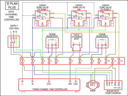
IF4 wiring manual datasheet, cross reference, circuit and application notes in pdf format. 1 Publication UMF-EN-P – April Summary of Changes To help you find new and updated information in this release of the manual, we have included .Micrologix Analog Module Help [Text] – schematron.org – Interactive Q & ARockwell Automation IF4 MicroLogix Analog Input Module : Manual
