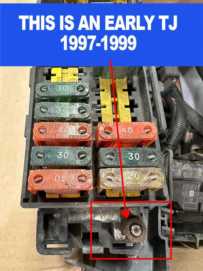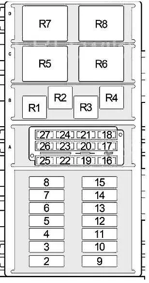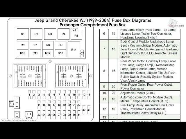
Locate the power distribution panel inside the cabin near the driver’s side for quick access to all circuit protectors. Each component is clearly marked with its specific amperage and function, ensuring precise identification for troubleshooting electrical issues.
Consult the factory service manual for an exact map of all protective devices, including those controlling the ignition system, lighting circuits, and auxiliary accessories. Accurate knowledge of each slot’s purpose prevents accidental disruptions and expedites repairs.
Check for labels inside the cover panel, which typically include a detailed schematic indicating all current ratings and circuit assignments. This resource is invaluable when replacing blown components or upgrading electrical parts safely.
Always disconnect the battery before removing or installing any protective device to avoid shorts or damage to the vehicle’s wiring harness. Proper handling safeguards sensitive electronics and maintains system integrity.
Fuse Layout and Identification for the 1999 Model SUV

Locate the primary electrical panel beneath the dashboard on the driver’s side for easy access. This panel controls the essential circuits and relays critical to the vehicle’s operation.
- Slot 1: Headlamp relay – 15A
- Slot 2: Horn and turn signals – 10A
- Slot 3: Ignition system – 20A
- Slot 4: Engine control module (ECM) – 15A
- Slot 5: Fuel pump relay – 20A
- Slot 6: Cooling fan – 30A
- Slot 7: Interior lighting – 10A
- Slot 8: Power windows and locks – 25A
- Slot 9: Air conditioning system – 10A
- Slot 10: ABS system – 30A
For under-hood electrical protection, check the secondary panel near the battery compartment. It houses high-amperage fuses for major components.
- Main power supply fuse – 40A
- Alternator fuse – 50A
- Starter relay fuse – 40A
- Radiator fan fuse – 30A
Always replace with fuses matching the specified amperage rating to prevent electrical failures. Use a test light or multimeter to confirm malfunctioning circuits before swapping elements.
Locating and Identifying the Electrical Panel in a 1999 Jeep Cherokee

The main power distribution panel is situated beneath the dashboard on the driver’s side, just below the steering column. To access it, remove the lower dash panel or kick panel by gently pulling it away or unscrewing fasteners if present.
An additional control center is located under the hood on the driver’s side fender well. This external panel houses high-amperage circuits and relays critical for engine and accessory functions.
Each fuse and relay slot in these compartments is labeled on the inside of the removable cover. For precise identification, cross-reference the printed layout on the cover with your vehicle’s owner’s manual or maintenance guide specific to the 1999 model.
Check amperage ratings printed on each component to avoid mismatching replacements, ensuring proper circuit protection and system reliability.
Interpreting the Electrical Panel for the 1999 Model
Start by identifying the layout of the electrical connections inside the panel. Each component is assigned a specific position and number for easy reference. The numbers and labels help in locating each circuit for troubleshooting or replacement. Consult the owner’s manual to match the positions with the corresponding components.
Pay close attention to the color coding. Different wire colors correspond to various circuits and functions, such as ignition, lighting, or air conditioning. Ensure that the connections are intact, and inspect the individual elements for signs of damage, corrosion, or wear.
Test each connection with a multimeter. A correctly functioning system will show continuity, while an open circuit will indicate a fault. If any circuit shows no continuity, check for a blown link or a faulty relay in the system.
When replacing a component or fuse, always follow the specified amperage for that circuit. Overloading can lead to further damage or system failure. The replacement part must meet or exceed the factory specifications to ensure safe and reliable operation.
Finally, verify that each section is securely reassembled after any work is completed. Loose or poorly connected components can cause intermittent issues, making it harder to diagnose the root cause of an electrical malfunction.
Replacing and Troubleshooting Fuses in a 1999 SUV

To restore electrical functionality in your vehicle, identify the faulty component by inspecting the power system. If an electrical accessory or system stops working, the issue is often a blown circuit protector. Begin by locating the power distribution panel, which typically sits beneath the dashboard or near the engine compartment.
Step 1: Always disconnect the battery before starting any repair to prevent shocks or damage to the electrical components.
Step 2: Find the specific protector that controls the malfunctioning system. Refer to the vehicle’s manual for the exact location. If the manual is unavailable, use a multimeter to check the continuity of each component in the panel.
Step 3: If a malfunctioning unit is located, remove it carefully. Examine it for any visible signs of damage such as discoloration or broken elements.
Step 4: Replace the faulty protector with a new one of the same type and rating. Ensure the new unit fits properly into the slot. Avoid using a higher rating to prevent potential damage to the electrical system.
Step 5: Reconnect the battery, then test the system to verify that it operates as expected. If the issue persists, double-check for any underlying problems such as faulty wiring or a defective electrical device.
Troubleshooting Tips:
- If the replacement protector blows immediately, there may be an underlying short circuit or overload. Inspect the related wiring and connections for damage or corrosion.
- Use a fuse puller tool to safely remove and install new components, avoiding direct contact with metal parts.
- For persistent issues, consult an expert to check for more complex wiring or component failures.
Prevention: Regularly inspect the electrical system, especially if unusual behavior is noticed. Replace damaged protectors promptly to avoid damage to the system’s components.