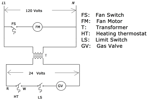
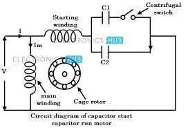
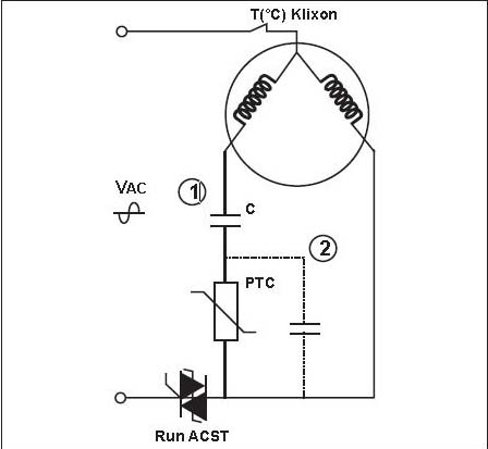
Most motors come with clear instructions or a wiring diagram on the side, however, some Here we will illustrate the proper wiring for a motor to a run capacitor. Motor start capacitors are used during startup phase of AC induction motors.
Read all about the capacitor properties, circuitry and applications. circuit diagram of motor start and motor run capacitor. wiring diagram for a motor starting capacitor.
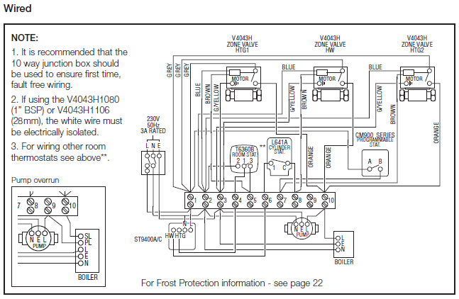
Here are some sample capacitor installation instructions for adding a motor starter capacitor to an air conditioning . The single-phase induction motor can be made to be self-starting in numerous ways.
Another method is the Capacitor Start Induction Run Motors. Thus a capacitor-start induction-run motor produces a better rotating magnetic field than the split-phase motors. If you have a single-phase three speed split capacitor motor, the following will the diagram below would be the complete connection diagram.Wiring a capacitor to start a motor begins with the connection of the positive terminal of the motor to the resistor. Take one terminal of the resistor, and connect it to the capacitor.
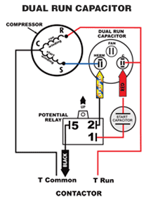
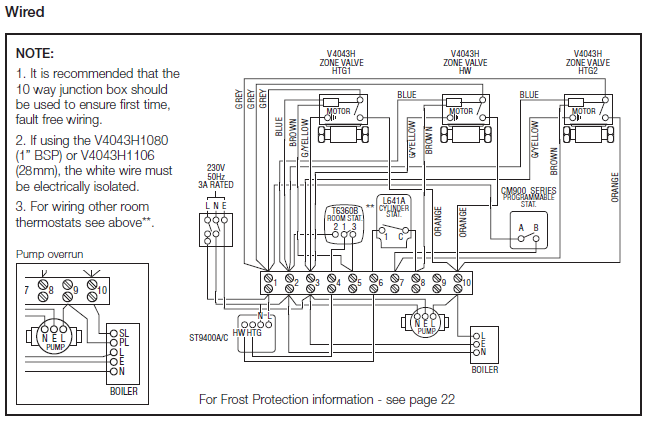
Read the wiring diagram on your appliance to understand the colors that the manufacturer designed for the three connections, namely, start, run and common. Push the wire terminal on the start capacitor’s second wire onto the run capacitor’s common terminal, often labeled “C,” “COM.” The wire connected to the motor’s run terminal, marked as “R” on the motor’s wiring chart, and the wire going to the hot terminal on the load side of the contactor also connects to this run capacitor terminal.
Jul 26, · How to wire single phase motor with capacitor. You will find out how to identify to main and auxilliary winding and change motor rotation.
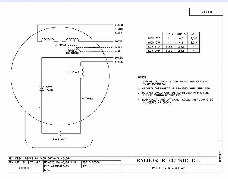
Start capacitor, run capacitor or permanent capacitor. Capacitor-Start Induction-Run Motors.
We know about the activity of a capacitor in a pure A.C. Circuit. When a capacitor is so introduced, the voltage lags the current by some phase angle.
In these motors, the necessary phase difference between the Is and Im is obtained by introducing a capacitor in series with the starter winding. Compressor Motor and Component Information.
17 C. Capacitor Start and Run (CSR) This motor arrangement uses a start capacitor and a run capacitor in parallel with each other and in series with the motor start winding.
This motor has high starting torque, runs efficiently, and is used on many refrigeration and air conditioning applications.How to Wire a Run Capacitor to a Motor Blower & Condenser HVAC WiringBaldor Start & Run Capacitors