For efficient operation of dual-stage ventilation units, proper connection of the control components is crucial. Focus on ensuring that the terminals for high and low settings are correctly linked to the power supply and control switches. This will enable the system to toggle between the two different intensity levels seamlessly.
First step: Check the power input requirements for both operational modes. It’s vital to match the input voltage to the correct terminal configurations to prevent overheating or damage to the system. The higher setting typically requires a higher voltage, while the lower one operates with reduced power.
Second step: Carefully connect the control switch to the appropriate terminals for each intensity. This will allow you to manually or automatically adjust between the two modes without causing strain on the components. Incorrect connections can lead to malfunctions or even electrical shorts.
Third step: Double-check the grounding of the entire system to ensure safety during operation. Proper grounding reduces the risk of electrical hazards and ensures smooth performance throughout its use.
Remember: Always consult the system’s technical manual before making adjustments to ensure compliance with manufacturer specifications.
Two-Stage Circulation Unit Connection Guide

To ensure optimal performance of a two-stage airflow system, connect the terminals correctly. Begin by linking the primary power supply to the main terminal. Use a wire rated for the required current to prevent overheating. The next step involves connecting the secondary terminal to the appropriate control switch, allowing for two operational settings.
Key considerations: Ensure each stage of the system has its designated wire path to avoid interference between settings. For multi-voltage systems, check voltage specifications before making connections. Incorrect configurations may lead to malfunction or damage.
Tip: Always refer to the technical manual for specific models to ensure correct voltage and amperage compatibility before making any connections.
Understanding the Components of a 2 Speed Fan Motor
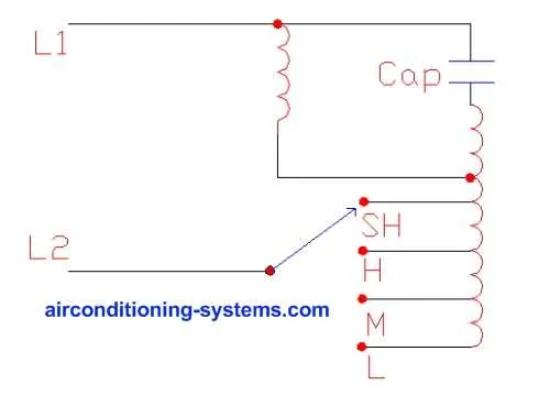
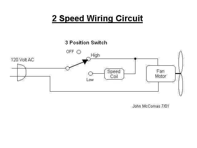
Start with the control switch: It determines the operation mode by regulating the electrical current. Typically, a two-position switch allows the user to alternate between the higher and lower settings, based on the connected windings in the unit.
Windings: Two distinct coil sets are used, each offering different resistance and power. One winding is designed for high capacity, while the other is for reduced output. These windings are crucial for adjusting the power based on demand.
Capacitor: The capacitor assists in modifying the phase shift in the motor’s current, improving efficiency and ensuring the coils are energized appropriately for different performance levels. Be sure to match the capacitor to the motor’s specifications for optimal function.
Commutator or Switch Contacts: These parts ensure proper selection of the right windings. They connect to the input from the power supply and activate the appropriate coil based on user input. Maintaining clean and undamaged contacts is critical to prevent malfunction.
Bearings and Shaft: Proper alignment and lubrication are essential for smooth operation. A misaligned shaft can lead to excessive wear and potential failure of the unit. Always ensure the shaft is balanced and rotates freely.
Step-by-Step Guide to Connecting a Dual-Rate Airflow Unit

To properly connect a two-speed airflow unit, follow these clear steps to ensure correct operation.
- Turn off power to the device to avoid any electrical hazards.
- Identify the terminals for both operational settings. Typically, there will be two separate connections for each performance level.
- For the lower capacity setting, connect the corresponding wire from the control unit to the designated terminal.
- Next, connect the wire for the higher setting to its respective terminal, ensuring it’s properly isolated from the lower setting connections.
- Locate the common wire, which is used to complete the circuit for both settings, and securely attach it to the corresponding terminal.
- Double-check all connections for any loose or exposed wires.
- Ensure that the ground wire is correctly attached to the grounding terminal to prevent electrical faults.
- After confirming all connections, turn on the power and test both modes to ensure proper functionality. The unit should transition smoothly between each performance level without issues.
Following these steps will guarantee a reliable and safe installation of your dual-setting airflow device.
Troubleshooting Common Electrical Issues in Dual-Rate Units
Check the capacitor first. A faulty or worn-out capacitor can cause irregular performance at different power settings. Test it using a multimeter set to measure capacitance and ensure the readings match the specifications marked on the component. If it’s out of range, replacing it should restore proper functionality.
If the unit is not responding to any setting, inspect the switch contacts. Over time, these can become corroded or dirty, leading to a loss of connection. Clean the contacts or replace the switch if necessary to ensure consistent operation across all modes.
Ensure all connections are tight and free of oxidation. Loose or corroded terminals can interrupt the electrical flow, resulting in uneven operation. Use a wire brush or sandpaper to clean any connections showing signs of wear or buildup.
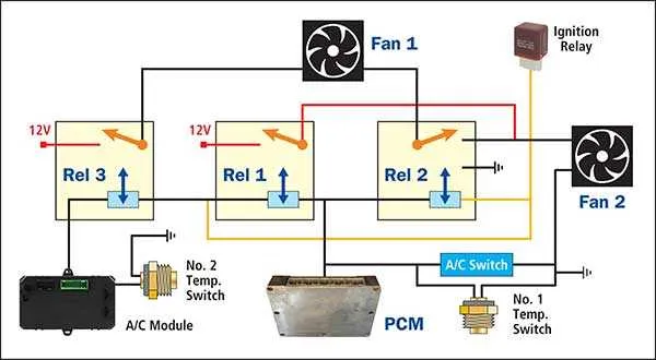
If the equipment operates intermittently, check the relay. A malfunctioning relay can cause erratic behavior, especially when switching between different settings. Replace any relay that does not activate smoothly or shows signs of overheating.
Finally, verify that the power supply meets the required voltage and amperage for optimal performance. Any deviation from the rated values can result in improper function, so use a voltmeter to ensure the input is stable and within the specified range.