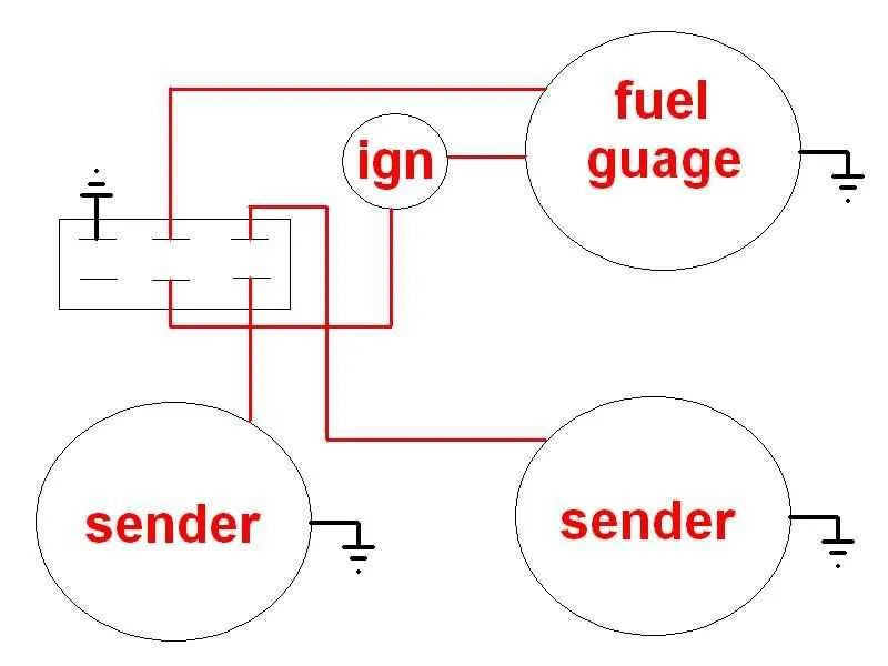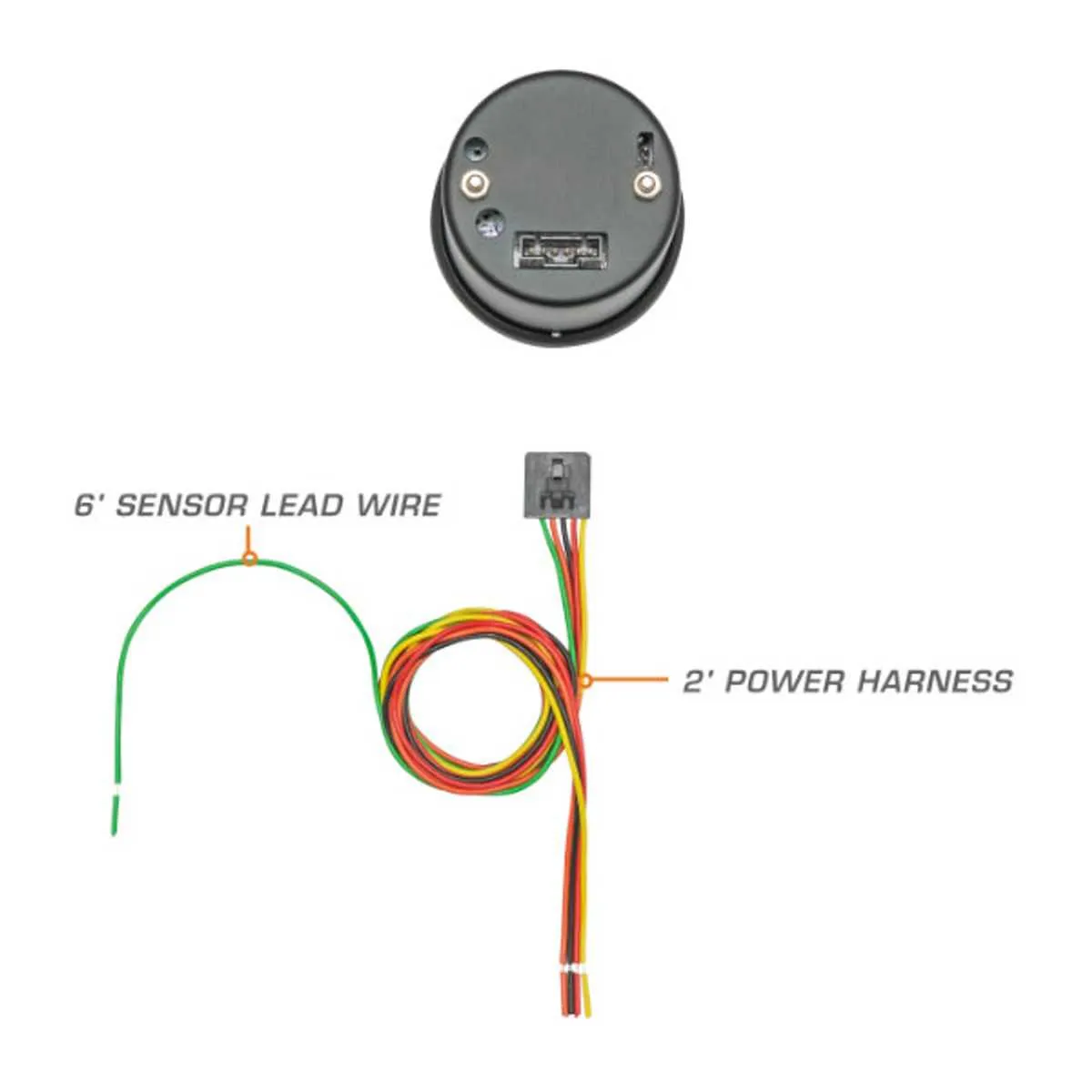
Connect the first line directly to a stable 12V ignition source. This ensures consistent voltage input when the vehicle is operational and prevents erratic readings caused by fluctuating power.
Attach the second line to the sensing unit’s variable resistor terminal. Resistance values typically range between 10 ohms (full) and 90 ohms (empty) in most automotive applications. Confirm compatibility with your display module before final connection.
Ensure that the sensing unit is properly grounded. An unreliable return path can lead to false outputs or complete signal failure. Use a verified chassis ground point to avoid introducing noise into the circuit.
When troubleshooting, check for continuity along the entire circuit and validate the resistance range using a multimeter. Inconsistent values may indicate corrosion, a break, or an incompatible sensor type.
To achieve precise readouts, avoid splicing the signal line with other circuits. This can introduce interference, leading to inaccurate panel responses. Always isolate the signal path for best performance.
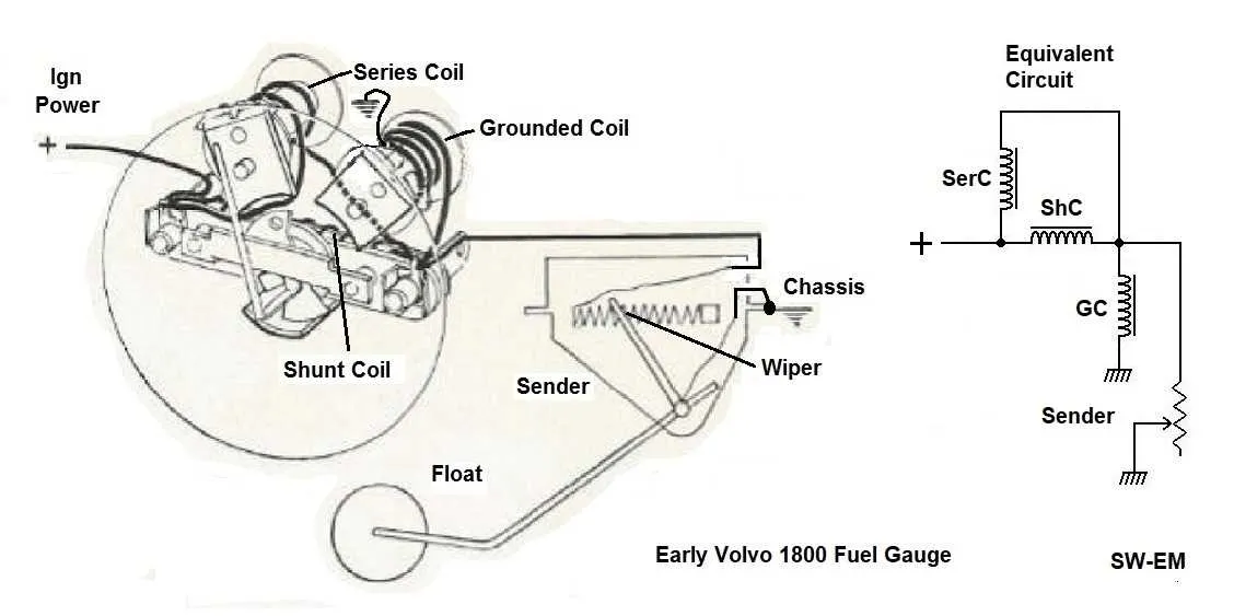
2 Wire Fuel Gauge Wiring Diagram
Connect the sensor’s negative terminal directly to the chassis ground to ensure accurate resistance reading. Avoid shared grounding with high-current components to reduce noise interference.
Route the sender’s output to the input terminal of the display unit. Ensure it supports the resistance range of typical senders–usually 240 ohms (empty) to 33 ohms (full) for American systems, or 0–180 ohms for European types.
Supply the indicator with a stable 12V source via the positive terminal. Use a fused connection rated at 1A to protect against short circuits.
If using LED-based indicators, verify that the input impedance does not affect the sensor’s resistance curve. Some digital units require signal conditioning with buffer circuits.
Minimize lead length between sender and display to prevent voltage drop. For installations exceeding 10 feet, opt for shielded conductors and place the shield on ground only at the receiving end.
Identifying the Signal and Ground Terminals on Common Gauges
Start by locating the rear terminals: most analog readout units feature two or three metal posts labeled with small letters or symbols. Look for a marking like S or SIG; this is typically the sensor input, which connects directly to the sender unit. If no label is present, measure resistance to chassis–terminals showing continuity to the casing usually serve as ground returns.
Use a multimeter in continuity mode: touch one probe to the device housing and probe each terminal. A reading close to zero ohms confirms the grounding pin. The remaining contact, especially if isolated, is often the data input. In some models, a third lug may provide positive voltage input; disregard it when working with dual-terminal setups.
For aftermarket or unmarked models, consult datasheets or identify by color conventions–black or brown commonly indicates the grounding point, while yellow or green typically carries the sensor data. Avoid trial-and-error methods, as reverse connections can damage internal coils or cause inaccurate readings.
Steps to Connect a 2-Wire Gauge to a Sending Unit

- Attach the primary conductor from the indicator to the sender terminal on the sensor. Ensure the link is secure and free of corrosion.
- Link the second line from the indicator directly to the negative terminal of the power source or a solid chassis ground.
- Inspect the sender body for proper grounding; if isolated, add a dedicated earth strap to maintain accurate readings.
- Ensure the power lead supplying the display unit is routed through a fuse (typically 1A) and connected to a switched ignition source.
- Confirm resistance values of the sensing element using a multimeter; typical ranges are 240Ω (empty) to 33Ω (full), but verify manufacturer specs.
- Once installed, test the assembly by manually varying the sender float or resistance and monitoring needle movement or digital output.
- Use shielded cabling if installation is near high-interference components to prevent signal fluctuation.
Troubleshooting Incorrect Readings in a Basic 2-Lead Setup

Begin by verifying the continuity of the two conductors using a multimeter; any resistance above 1 ohm can cause signal distortion. Check the connection points for corrosion or looseness, as poor contact often leads to fluctuating values. Ensure the reference voltage matches the device specifications, typically 3.3V or 5V, to prevent offset errors.
Inspect for electromagnetic interference nearby, especially from motors or ignition coils, which can introduce noise and false data. Use shielded lines or add ferrite beads if necessary. Confirm polarity alignment between sensor terminals and measurement inputs–reversed polarity will yield incorrect output.
Measure the system’s ground integrity; a weak ground can cause floating readings. Grounds should be connected to a low-resistance chassis point. Test the device with a known good reference to isolate hardware faults. If the issue persists, replace the sensing element, as aging components degrade accuracy over time.