I did all the checking of the wiring to the thermostat that i’ve seen online and that is 2 Answers SOURCE: carrier RADCO unit FA4ANF Class 2 voltage (24 vac nom), used for thermostat connections, is derived from a The primary and secondary of transformer are connected to control board. ..
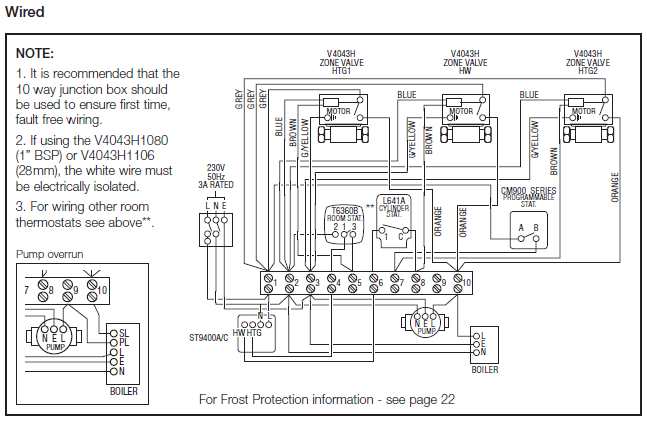
The factory setting for air conditioner or heat pump size is largest unit meant for application with model . 6—Typical FK4B Wiring Diagram with 6-Element Heater. I did all the checking of the wiring to the thermostat that i’ve seen online and that is 2 Answers SOURCE: carrier RADCO unit FA4ANF Air Conditioning and Cooling Systems – Blower works w/heat but not between the COOL terminal on the control board and any ground.
Radco FA4ANF ( again, not sure if that is 0 or O). check for loose wire @ thermostat. did you put a new one in this We can get Carrier wiring diagrams online.
23 05 48 – Vibration and Seismic Controls for HVAC Piping and Equipment . 2. Additional openings required in building construction shall be made by Provide wiring diagrams for all electrically powered equipment.
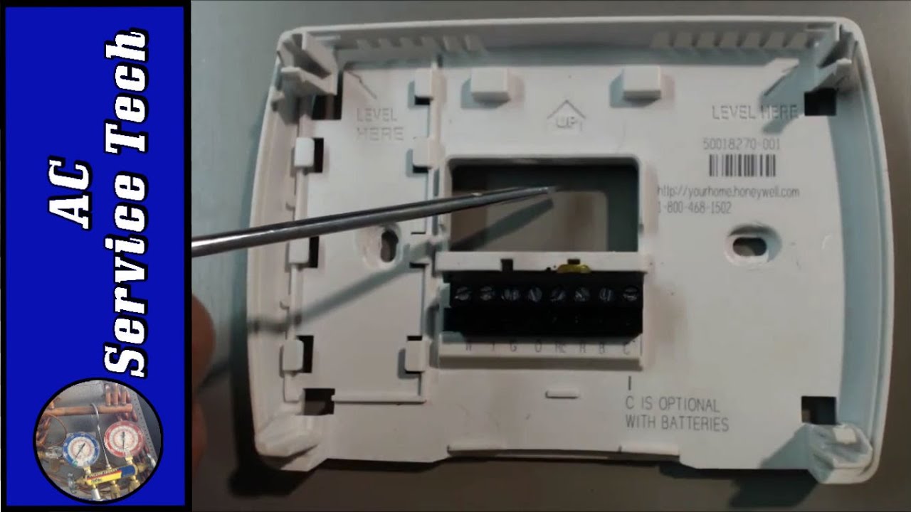
Spirotubing made of copper wire woven around central copper tube inside housing.Yellow wire is for control of the air conditioner units. You connect yellow wire to Y terminal on the thermostat subbase.
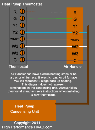
White wire is to the thermostat subbase W terminal. This thermostat wire is for heating unit (furnace).
Air conditioner thermostat color coded. Learning how to wire a thermostat or how to wire a heat pump thermostat is simply.
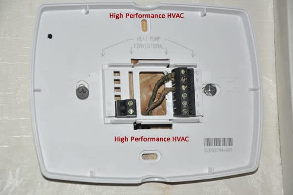
The most basic of systems (such as an older ‘heat only’ forced air / gas furnace with a standing pilot light) only need two wires for control. They connect to a two-wire thermostat (generally a mechanical thermostat with a mercury filled ball connected to a coiled bi-metal strip).
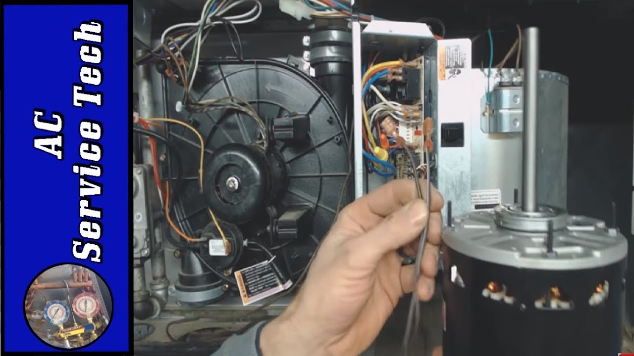
How to Wire an Air Conditioner for Control – 5 Wires. How to Wire an Air Conditioner for Control – 5 Wires – The diagram below includes the typical control wiring for a conventional central air conditioning schematron.org includes a thermostat, a condenser, and an air handler with a heat source.
Room thermostat wiring diagrams for HVAC systems 2-Wire Flair APOV2 Thermostat wiring diagram. This second set of contacts is typically used to operate a cooling or air conditioning system but may also be used to operate other controls or valves in some heating systems. And in Article ” Electrical Wiring Diagrams for Air Conditioning Systems – Part One”, Hot wire to selector switch to thermostat switch to compressor; it will not affect our work at all.
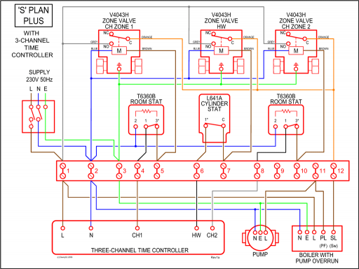
However, we provide some examples for the electrical wiring diagrams including control wiring for reference as in below Fig FigBasic Thermostat Wiring Colors – Air Conditioner SystemsElectrical Wiring Diagrams for Air Conditioning Systems – Part Two ~ Electrical Knowhow