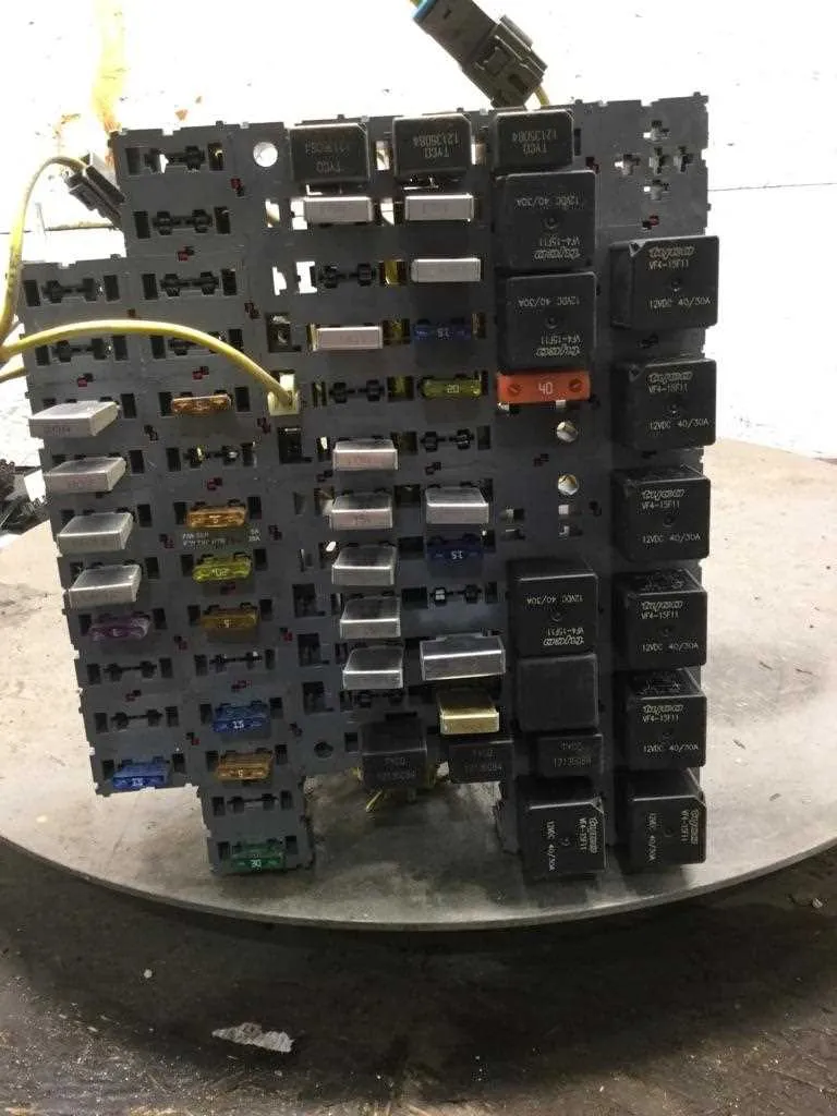
When working on your truck’s electrical system, a clear understanding of its wiring components is essential for diagnosing and fixing issues. Identifying the correct connectors and their functions within the vehicle’s circuitry can save time and effort when performing repairs. It’s important to start by locating the essential components that manage the flow of electricity to various systems, such as the engine, lighting, and climate control. The following guide provides a clear layout of these connections, focusing on the critical components that are most prone to wear and failure.
Begin with the Primary Circuitry–start by locating the main distribution block. This is where power is distributed throughout the vehicle to different subsystems. Each terminal within this block serves a specific function, such as powering the ignition, lights, or auxiliary devices. Check for any blown or loose connectors, as these can cause electrical faults that affect vehicle performance.
Secondary Components and Their Functions–once the primary circuit is understood, the next step is to address the auxiliary connections. These are responsible for smaller systems like air conditioning, sensors, and other add-ons. Some of these may require more in-depth analysis to trace back to their origin points, especially if issues like intermittent power loss occur.
By following this systematic approach, you can more easily pinpoint electrical issues and restore full functionality to your vehicle. Take care to document any changes or replacements made to ensure that future troubleshooting becomes simpler and more efficient.
Electrical System Overview for the 2000 Model
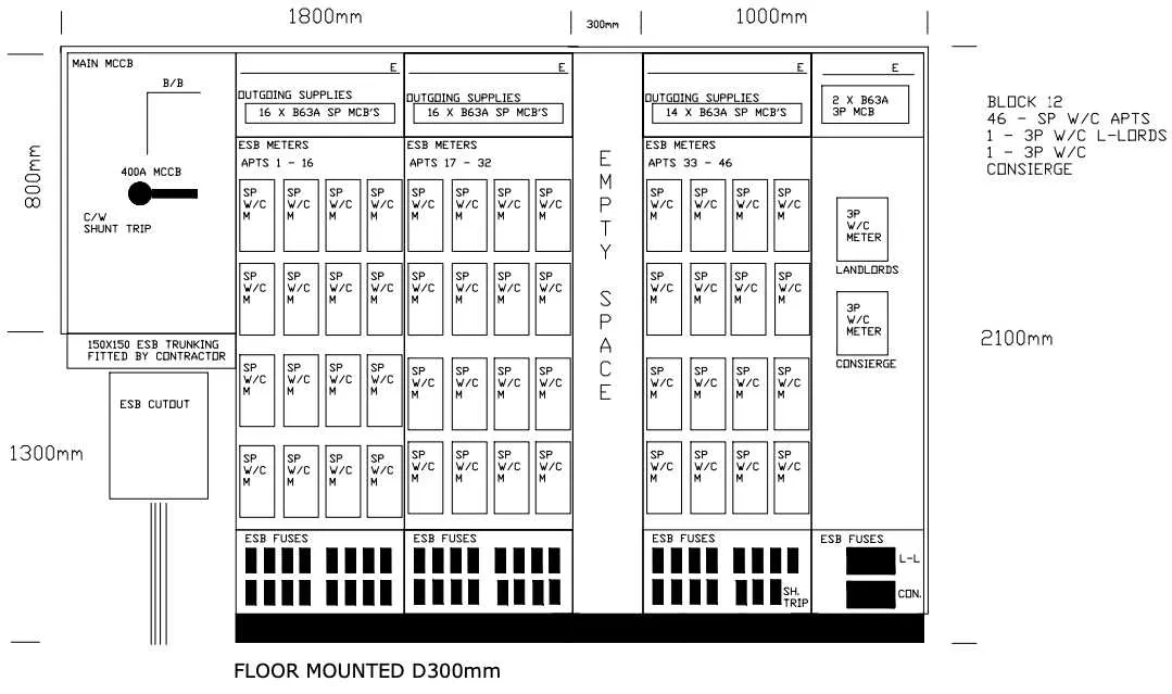
Refer to the electrical schematic to locate the main circuit blocks and identify the necessary components for troubleshooting. The power distribution layout in this vehicle includes multiple sections dedicated to essential systems such as lighting, engine control, and safety devices. Proper identification of the right components ensures smooth operation and reduces downtime.
The primary distribution is divided into two sections: one located inside the cabin and another beneath the vehicle’s chassis. Be sure to check each segment carefully, as they control specific functions such as interior lighting, climate control, and engine management. Fuses are typically labeled based on their function, making it easier to trace power issues back to their source.
In case of a malfunction, start by inspecting the main blocks that power critical systems. Each unit is designed to protect sensitive equipment by interrupting the circuit in case of a power surge or short. Ensure that the amperage ratings match the manufacturer’s specifications for optimal performance. If a fuse appears to be blown, replace it with one of the same rating to avoid further damage.
Regularly checking and maintaining these power distribution elements will prevent issues related to electrical failures and improve overall reliability. Keep a copy of the diagram handy for quick reference during maintenance tasks, especially when working with complex electrical components.
Locating and Understanding the Fuse Layout
To access the electrical protection system in your vehicle, first identify the location of the control board. Typically, it can be found under the dashboard or in the engine compartment, depending on the model configuration.
Once located, you will notice several slots and connections, each assigned to specific functions. These include components such as lights, ignition, and power outlets. To simplify identification, follow these steps:
- Refer to the vehicle’s user manual for precise placement of components and their corresponding connections.
- Inspect the housing for labels or indicators next to each connection, which will guide you to the relevant circuit.
- Use a test light or voltmeter to verify continuity and check the functionality of each slot.
For easy maintenance, keep a map or chart of the various circuits in the vehicle. This will help when troubleshooting or replacing damaged connectors.
Be cautious when working with the electrical system–ensure the power is turned off before making any adjustments to prevent injury or damage to the vehicle.
Identifying Key Fuses and Their Functions in the W900

Check the power distribution system regularly to ensure the electrical components are working properly. If a circuit fails, inspect the relevant protective elements to pinpoint the issue quickly. Key electrical circuits in the vehicle are typically controlled by the main power distribution, located under the dash or in the engine compartment.
The primary control for the lighting system is often located in the fuse block near the dashboard. For headlamps and tail lights, look for the designated slots, which are typically labeled. If the headlights fail, this component is usually the first to check.
For auxiliary equipment like air conditioning or entertainment systems, the related components are often placed within separate holders, commonly situated near the main section for easy identification. Air conditioning failure typically signals a fault in the auxiliary system circuit.
Instrument cluster and dashboard electrical failures are usually linked to circuits found in the control center; inspecting the main relay and its surroundings will typically resolve issues. Electrical malfunctions affecting the engine or transmission sensors can often be traced to the specialized components handling their signals.
Lastly, ensure that the safety and braking systems have functioning protection by checking the relays governing these vital circuits. It’s crucial to inspect these elements carefully, as they may affect vehicle operation and safety. Always replace any damaged components immediately to maintain vehicle integrity and safe operation.
How to Troubleshoot Common Electrical Issues in the 2000 Kenworth W900
Start by inspecting the main power distribution box located under the dashboard, where critical circuits are connected. Use a multimeter to check for continuity across each circuit. If you detect a break, the corresponding component may not be receiving power. Replace or rewire any damaged connections.
Next, check the specific terminals associated with accessories like lights, horn, and radio. Often, a faulty connection or corrosion can prevent proper functioning. Cleaning the terminals and applying dielectric grease may resolve minor issues without replacing parts.
For components that require a ground connection, ensure the grounding points are clean and tightly secured. A loose or corroded ground can result in intermittent failures. Clean the ground connection with a wire brush and reattach it firmly to the frame or chassis.
Another important step is to verify if any circuit has overheated. Discoloration or burnt marks on the wires or connectors indicate potential short circuits or overloads. Replace the damaged wires and inspect the system for the root cause, such as mismatched components or improper installation.
In case of a sudden electrical failure, remove and inspect the corresponding relays. A faulty relay often causes issues by not allowing proper current flow. Swap with a known working relay and check for restoration of functionality.
For systems that remain unresponsive after these checks, it’s advisable to consult the vehicle’s electrical schematic. Follow the wiring paths to ensure all connections are properly aligned and there are no hidden breaks in the circuit.