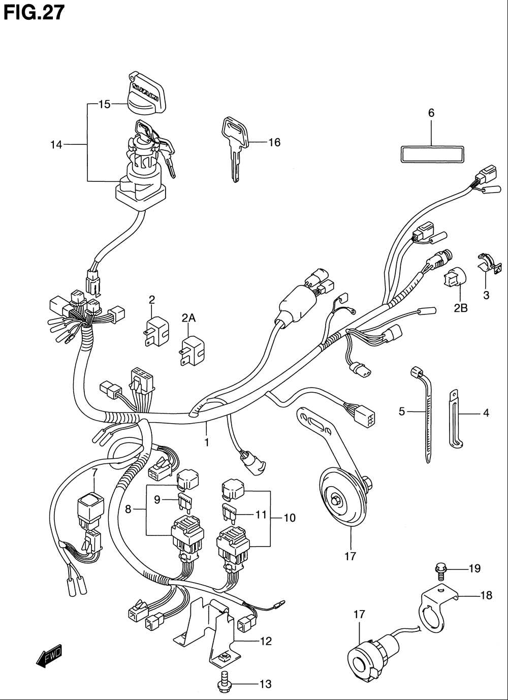
If you are the proud owner of a 2001 Yamaha Big Bear 400 ATV, having a good understanding of its wiring diagram can be immensely helpful. The diagram is a visual representation of the electrical system in your ATV and serves as a roadmap for troubleshooting and repairing electrical issues.
The wiring diagram for the 2001 Yamaha Big Bear 400 shows the various electrical components and their connections. It illustrates the wiring for the ignition switch, starter relay, fuel pump relay, lights, and other electrical components. With this diagram, you can easily identify which wires are responsible for powering specific parts of your ATV.
Having a wiring diagram is especially useful when dealing with electrical problems. If you are experiencing issues such as a no-start condition, malfunctioning lights, or a faulty ignition switch, the wiring diagram can help you pinpoint the problem area and make the necessary repairs. It can also be useful for installing aftermarket accessories or modifying the electrical system.
Whether you are a seasoned ATV enthusiast or a novice owner, having access to a comprehensive wiring diagram can save you time, money, and frustration. By familiarizing yourself with the electrical system of your 2001 Yamaha Big Bear 400, you can troubleshoot and repair electrical issues with confidence.
Understanding the Wiring Diagram for the 2001 Yamaha Big Bear 400
The 2001 Yamaha Big Bear 400 is a popular off-road vehicle known for its durability and reliability. When it comes to understanding the wiring diagram for this ATV, it is important to have a clear understanding of the electrical components and how they are connected.
The wiring diagram for the 2001 Yamaha Big Bear 400 provides a visual representation of the electrical system, including all the wires, connectors, and components. It is a valuable resource for troubleshooting electrical issues and making repairs. The diagram uses symbols and colors to represent different components and their connections.
One important component in the wiring diagram is the ignition switch. The ignition switch is responsible for controlling the electrical power to the ATV’s various systems. It is connected to the battery, starter, and other components. Understanding how the ignition switch is wired can help diagnose problems with starting the ATV or powering certain systems.
Another crucial component in the wiring diagram is the CDI (Capacitor Discharge Ignition) unit. The CDI unit is responsible for controlling the ignition timing and firing the spark plugs. It receives information from various sensors and switches, such as the throttle position sensor and the kill switch. By understanding how the CDI unit is connected, it is easier to troubleshoot ignition problems.
In addition to the ignition switch and CDI unit, the wiring diagram also includes information about the ATV’s lighting system, charging system, and other electrical components. It shows how these components are connected to each other and to the battery. This information is useful for diagnosing issues with the ATV’s lights, battery charging, and other electrical systems.
In summary, understanding the wiring diagram for the 2001 Yamaha Big Bear 400 is essential for troubleshooting electrical problems and making repairs. It provides a visual representation of the ATV’s electrical system, including the ignition switch, CDI unit, and other components. By studying the diagram, ATV owners can gain a better understanding of how their vehicle’s electrical system works and how to fix any issues that may arise.
Components of the Electrical System
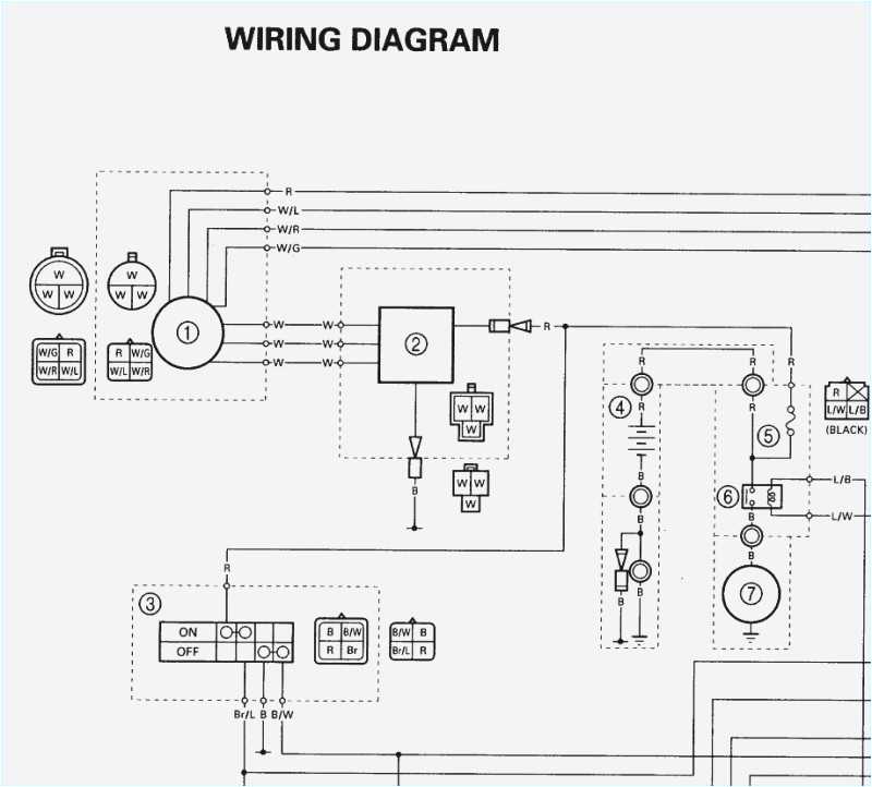
The electrical system of a 2001 Yamaha Big Bear 400 consists of several components that work together to provide power and control for various functions of the ATV. These components include the battery, starter motor, ignition switch, wiring harness, fuses, relays, switches, and various sensors.
The battery is the primary source of electrical power for the ATV. It stores and supplies the electrical energy needed to start the engine and operate the electrical systems. The starter motor is connected to the battery and is responsible for turning the engine over when the ignition switch is turned on.
The ignition switch is a key-operated switch that controls the flow of electrical power to the ATV. It has multiple positions, including “off,” “on,” and “start.” When the ignition switch is turned on, power is supplied to the various electrical systems of the ATV.
The wiring harness is a collection of wires that connect the various electrical components of the ATV. It provides a pathway for electrical current to flow between the battery, ignition switch, and other components. The wiring harness is designed to be durable and withstand the rugged conditions of off-road riding.
Fuses and relays are electrical safety devices that protect the electrical system from damage caused by overload or short circuits. Fuses are designed to blow when excessive current flows through them, while relays are electrical switches that control the flow of current to different components.
Switches are used to control the operation of specific functions, such as lights, turn signals, and accessories. They can be mechanical switches that are physically manipulated, or electronic switches that are controlled electronically. Various sensors are also used in the electrical system to monitor and regulate different parameters, such as engine temperature and tire pressure.
Wiring Diagram Overview
The wiring diagram for the 2001 Yamaha Big Bear 400 provides a detailed overview of the electrical system of this ATV. It shows the connections and paths of the various electrical components, allowing for easy troubleshooting and repair. The diagram is divided into several sections, each representing a different aspect of the electrical system.
One of the main sections of the wiring diagram is the ignition system. It shows how the ignition switch, starter relay, and ignition coil are connected, enabling the ATV to start and run. The diagram also indicates the various wires that are involved in the ignition system, allowing users to easily identify and test them if necessary.
Another important section of the wiring diagram is the lighting system. This includes the headlights, taillights, brake lights, and turn signals. The diagram shows how these lights are connected to the battery and switch, as well as any other components involved in controlling the lighting system.
The wiring diagram also provides information on the charging system, which includes the alternator and battery. It shows how the alternator generates electricity and how it is connected to the battery for charging. This section also includes any fuses or relays involved in the charging system.
In addition to these sections, the wiring diagram may include information on other electrical components, such as the electric starter, fuel gauge, or speedometer. It provides a comprehensive overview of the entire electrical system of the ATV, allowing users to understand how all the components are connected and work together.
Understanding the Key Symbols and Markings
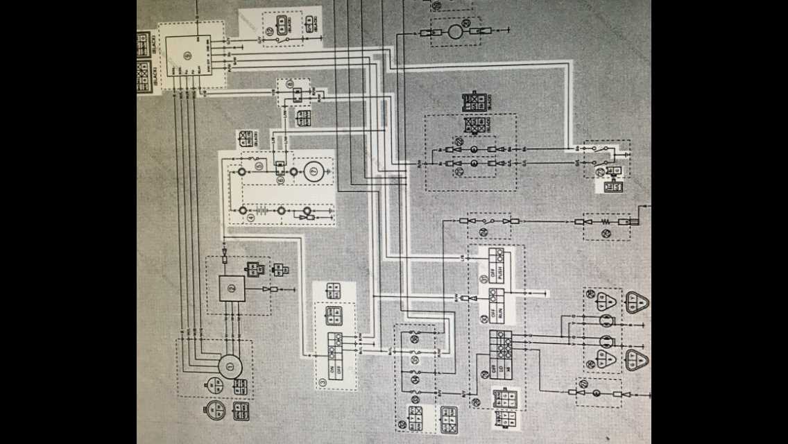
Gaining a clear understanding of the key symbols and markings that are present in a wiring diagram is crucial when it comes to reading and interpreting the information correctly. These symbols serve as visual representations of various components, connections, and electrical pathways within a system, and being able to recognize and decipher them accurately is essential for troubleshooting and repairs.
Here are some key symbols and markings commonly found in wiring diagrams:
- Lines: Lines in a wiring diagram represent electrical connections between components. These lines can be straight, curved, or dashed, and different line styles may indicate different types of connections, such as wires or cables.
- Boxes: Boxes or rectangles are often used to represent components in a wiring diagram. The component’s name or identification number is usually written inside the box, and additional markings or symbols may indicate specific features or properties of the component.
- Arrows: Arrows are commonly used in wiring diagrams to indicate the flow of electrical current. They typically point in the direction of the current flow, and their presence can help identify the sequence of operations or the path of the electrical circuit.
- Symbols: Various symbols are used to represent specific types of components or electrical elements in a wiring diagram. These symbols can include resistors, capacitors, switches, transformers, and more. Each symbol has a unique shape or design that corresponds to the type of component it represents.
- Colors: Colors are often used in wiring diagrams to differentiate between different wires or electrical connections. Each color may have a specific meaning or purpose, such as indicating a specific voltage level or signal type. It is essential to refer to a legend or key provided with the diagram to understand the significance of each color used.
By familiarizing yourself with these key symbols and markings, you can effectively navigate and interpret wiring diagrams, allowing you to troubleshoot and repair electrical systems with accuracy and confidence.
Step-by-Step Guide to Reading the Wiring Diagram
When it comes to working with the wiring diagram for a 2001 Yamaha Big Bear 400, it’s important to have a clear understanding of how to interpret the information provided. This step-by-step guide will help you navigate through the diagram and make sense of the electrical connections and components.
Step 1: Identify the Components
Start by identifying the various components that are represented in the wiring diagram. Look for symbols that represent the battery, ignition switch, lights, starter motor, and any other electrical devices or systems specific to the Big Bear 400.
Step 2: Understand the Wiring Connections
Next, familiarize yourself with the different types of wiring connections illustrated in the diagram. Look for lines, dots, or other symbols that indicate the electrical pathways between the components. Pay attention to the color-coding of the wires, as this will provide important information about their function.
Step 3: Follow the Flow of the Diagram
Once you understand the components and wiring connections, start following the flow of the diagram. Begin at the battery and trace the electrical pathways to different components, making note of any junctions, switches, or relays along the way. Take your time to ensure you accurately follow the diagram and understand the relationships between the components.
Step 4: Analyze the Labels and Values
As you navigate the wiring diagram, pay attention to any labels or values associated with the components or wiring. These labels may provide additional information such as voltage ratings, resistance values, or specific wire sizes. Understanding these details can help you troubleshoot and diagnose electrical issues more effectively.
Step 5: Refer to the Key or Legend
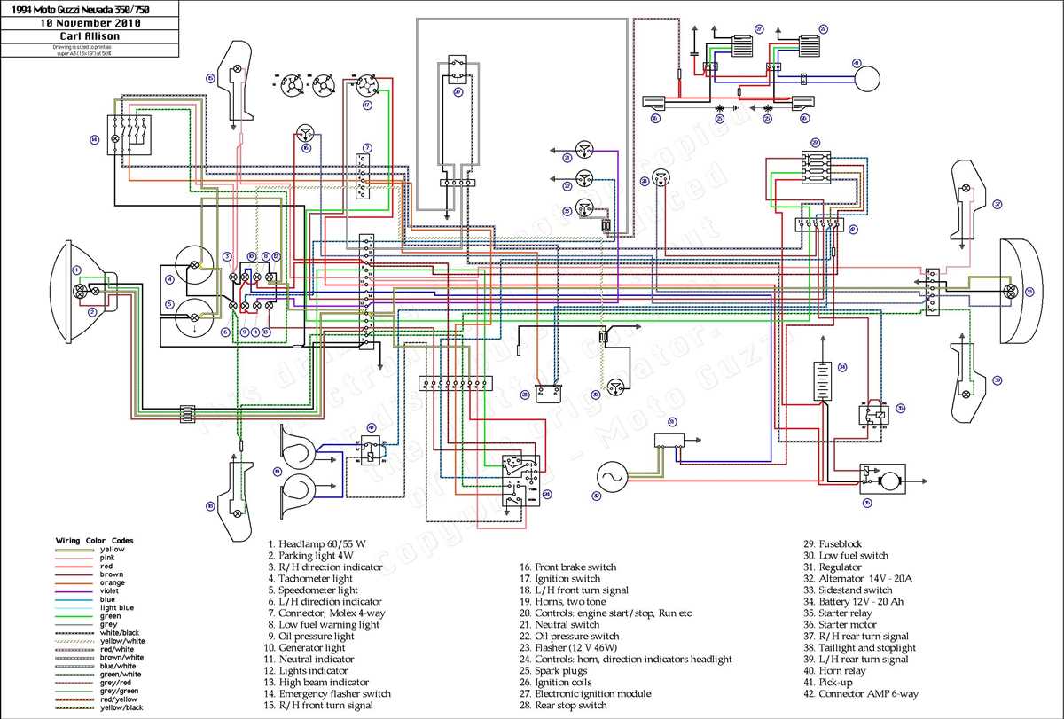
If the wiring diagram includes a key or legend, consult it to ensure you correctly interpret the symbols, colors, and other notations used in the diagram. The key or legend will provide definitions and explanations that can clarify any confusion or uncertainty you may encounter while reading the diagram.
Step 6: Take Notes and Make Connections
As you work through the wiring diagram, take notes, make connections, and mark any important information or points of interest. This will help you reference specific details later on and ensure you have a clear understanding of the electrical system in the Big Bear 400.
By following this step-by-step guide, you’ll be able to effectively read and interpret the wiring diagram for a 2001 Yamaha Big Bear 400. This understanding will enable you to troubleshoot electrical issues, make repairs, and maintain the electrical system with confidence.
Troubleshooting Common Electrical Issues
Electrical problems can be a frustrating and time-consuming issue to deal with on any vehicle, including the Yamaha Big Bear 400. However, armed with a basic understanding of the common electrical issues that can occur, you can save yourself time, money, and headache by troubleshooting and resolving them yourself. Here are some of the most common electrical issues that riders may encounter with the Yamaha Big Bear 400:
- Dead Battery: If your Yamaha Big Bear 400 is not starting or the lights are not turning on, the first thing to check is the battery. A dead or weak battery can prevent the ATV from starting or running properly. Check the battery voltage using a multimeter and recharge or replace it if necessary.
- Blown Fuse: If specific electrical components, such as lights or the ignition system, are not working, there may be a blown fuse. Locate the fuse box on your Yamaha Big Bear 400 and check the fuse corresponding to the malfunctioning component. Replace any blown fuses with the correct amperage rating.
- Wiring Issues: Check the wiring harness of your Yamaha Big Bear 400 for any loose or damaged wires. Look for any signs of corrosion, fraying, or chafing. Repair or replace any damaged wires as needed.
- Faulty Switches or Relays: If certain electrical components are not responding or functioning correctly, it may be due to a faulty switch or relay. Test the switches and relays using a multimeter to determine if they are working properly. Replace any faulty switches or relays as necessary.
- Stator or Charging System Problems: If you are experiencing issues with the battery not charging or the ATV losing power while running, there may be a problem with the stator or charging system. Test the stator and charging system using a multimeter and consult your Yamaha Big Bear 400’s service manual for specific testing procedures. Replace any faulty components as needed.
It is important to approach troubleshooting electrical issues with caution and patience, as improper handling can lead to further damage or even personal injury. If you are unsure about how to diagnose or fix an electrical problem on your Yamaha Big Bear 400, it is always recommended to consult a professional mechanic or refer to the ATV’s service manual for guidance. By properly troubleshooting and resolving common electrical issues, you can ensure that your Yamaha Big Bear 400 stays reliable and ready for your next off-road adventure.
Q&A:
What should I do if the power goes out in my house?
If the power goes out in your house, the first thing you should do is check the circuit breaker or fuse box to see if any breakers have tripped or fuses have blown. If everything seems fine there, you can check with your neighbors to see if they are also experiencing a power outage. If it’s just your house, you may need to contact your electricity provider to report the outage and schedule a repair.
Why do my lights flicker sometimes?
There are several possible reasons why your lights flicker. It could be due to a loose or faulty light bulb, a loose connection in the wiring, a problem with the circuit breaker, or a voltage fluctuation. If the flickering is isolated to one light fixture, try replacing the light bulb to see if that resolves the issue. If the problem persists or is affecting multiple lights, it’s best to consult a professional electrician for further troubleshooting.
What should I do if my electrical outlets are not working?
If your electrical outlets are not working, check to see if the circuit breaker or fuse corresponding to those outlets has tripped or blown. If that doesn’t seem to be the issue, you can try resetting the GFCI (Ground Fault Circuit Interrupter) outlets in your home. These outlets have a small reset button that can trip and cut off power to other outlets if a fault is detected. If none of these solutions work, it’s recommended to call a licensed electrician to assess and repair the problem.
Why does my circuit breaker keep tripping?
A circuit breaker trips when it detects an overload or a short circuit in the electrical circuit it protects. This can happen if you have too many appliances or devices running on the same circuit, or if there is a fault in one of the devices causing it to draw excessive current. To troubleshoot this issue, try unplugging some devices from the circuit and see if the breaker stops tripping. If it continues to trip, there may be a more serious problem with the wiring or the breaker itself, and you should contact an electrician for assistance.
What should I do if I get an electric shock?
If you get an electric shock, the first thing you should do is remove yourself from the source of electricity. Do not touch the person who is still in contact with the electric current, as this can result in a secondary shock. Once you are away from the source, assess the person’s condition and call for medical help if necessary. It’s important to seek medical attention even if the shock seems minor, as there can be internal injuries that are not immediately visible. Additionally, make sure to have a licensed electrician inspect the electrical system to identify and fix the problem that caused the shock.
How do I troubleshoot a circuit breaker that keeps tripping?
If your circuit breaker keeps tripping, it could be due to a few different issues. First, check to see if you have any overloaded circuits. If you have too many appliances or devices connected to one circuit, it can cause the breaker to trip. Try unplugging some items and see if the breaker stays on. If that doesn’t solve the issue, it could be a wiring problem or a faulty breaker. In that case, it’s best to call a licensed electrician to assess and fix the problem.
Why does my light bulb keep burning out quickly?
If your light bulbs are burning out quickly, there could be a few reasons. First, check to make sure you are using the correct wattage bulb for your fixture. Using a bulb with a higher wattage than recommended can cause it to burn out faster. Additionally, poor wiring or a loose connection can cause bulbs to burn out quickly. If the issue persists, it could indicate a larger electrical problem and it’s best to contact a professional electrician to investigate and fix the issue.