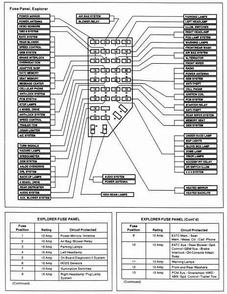
For easy identification of the various electrical components, it is crucial to understand the layout of the vehicle’s primary power distribution system. Begin by locating the main power distribution unit and carefully inspecting the internal structure, including the positioning of relays and connectors. This will help you efficiently address any issues related to power interruptions or electrical malfunctions.
Key components to focus on include the main power supply terminal, ground connections, and individual circuits for vital systems such as lighting, climate control, and engine management. Each terminal or connection serves a specific purpose, ensuring the overall functionality of the vehicle’s electronic systems.
If you’re troubleshooting specific electrical issues, always refer to a detailed map of the system’s layout, where each terminal and relay is labeled for easier diagnosis. Make sure to check the integrity of each connection, ensuring no corrosion or loose wires that could disrupt electrical flow.
Regular maintenance of these components, such as cleaning terminals and replacing damaged connectors, will prolong the life of the system and prevent costly repairs down the line.
Fuse Location and Function for the 2002 Vehicle Model
Start by checking the main electrical panel located inside the cabin, near the driver’s seat. This panel houses crucial connections for interior features such as lights, radio, and HVAC systems. Make sure to identify the labels corresponding to each relay and fuse to avoid damage while working on any component.
The under-hood terminal is responsible for managing high-power components like the air conditioning and the powertrain system. Here you will find larger fuses that protect major systems. Before proceeding with any repairs or maintenance, ensure the terminal is disconnected to prevent electrical shocks.
Below is a table outlining the most common components and their fuse specifications:
| Component | Fuse Rating | Location |
|---|---|---|
| Headlights | 15A | Cabin |
| Windshield Wipers | 20A | Cabin |
| Power Windows | 30A | Cabin |
| Engine Control Module | 30A | Under-Hood |
| Air Conditioning | 40A | Under-Hood |
Double-check the electrical components before replacing any units to ensure compatibility with the fuse ratings. If unsure, consult the vehicle’s manual for further details on each individual part’s protection setup.
Understanding the Location of Electrical Panels

To easily locate the electrical panels in your vehicle, start by checking common areas known for housing these components. Typically, you’ll find one inside the cabin and another under the hood.
- The interior panel is often positioned beneath the dashboard on the driver’s side, near the steering wheel or under a plastic cover. It may also be found near the footwell or by the driver’s seat.
- The second panel is usually situated in the engine compartment, close to the battery or along the side of the engine bay, protected by a cover to prevent exposure to the elements.
Consult the owner’s manual for exact locations and the proper removal techniques. Always ensure that the engine is off and the vehicle is in park before accessing these compartments for safety.
Identifying Functions and Layout

Start by checking the central panel located under the dashboard on the driver’s side. Each slot corresponds to a different system or component in the vehicle, with numbers assigned to individual slots for easy identification. Examine the labeling carefully, as it typically includes system names like lights, climate control, and radio.
The relays are placed in dedicated areas to manage high-power systems, such as the engine and air conditioning. Look for the larger components positioned at the top of the panel for these tasks.
Ensure you have a clear view of the layout by removing any protective covers. A close inspection reveals which components handle auxiliary features, like power seats or rear wipers, by locating them towards the edges of the panel.
If you’re troubleshooting, cross-reference the numbers and labels with the relevant section in the owner’s manual for confirmation. This method ensures you’re addressing the correct component, particularly for systems requiring specific amperage protection.
For more accurate repairs or replacements, use a diagram from a repair manual that shows the exact positions and electrical details of the modules and their connections. Pay close attention to any colored markings as they often indicate particular functions or circuits.
Common Electrical Issues and Troubleshooting Tips
If a specific function or component stops working, check the power distribution system first. Often, the issue lies in a blown component that needs replacement. If the electrical connection is faulty, it can cause the device to malfunction intermittently or completely stop. Start by inspecting the power relay circuits for any signs of burn marks or corrosion.
For persistent electrical malfunctions, inspect the control panel connections. A loose or corroded wire can easily disrupt communication between circuits, leading to failures. Make sure all wires are securely connected and not worn out. Cleaning the connectors can help resolve minor disruptions.
When diagnosing malfunctioning components, always ensure that you’re using the correct replacement. Installing the wrong type of component can cause further damage, or not solve the issue at all. Be sure to cross-check part numbers with a repair guide or manufacturer specifications.
If you experience sudden power surges or inconsistencies, it might indicate a problem with the voltage regulation system. Test the electrical system with a multimeter to check for abnormal voltage readings. Excessive fluctuations could point to an internal fault in the distribution system.
Lastly, an often-overlooked troubleshooting step is verifying the grounding of the system. A poor ground connection can lead to erratic electrical behavior. Check the grounding wires for any signs of wear or detachment, and ensure they are securely connected to a solid, clean grounding point.