
If you own a 2006 PT Cruiser and are experiencing issues with your vehicle’s PCM (Powertrain Control Module) wiring, then you’re in the right place. The PCM is an essential component that controls various systems in your vehicle, including the engine, transmission, and emissions. Understanding the wiring diagram for your PT Cruiser’s PCM can help you troubleshoot and repair any electrical issues that may arise.
The PCM wiring diagram provides a detailed layout and connection information for the various wires and connectors that make up the PCM’s electrical system. This diagram serves as a roadmap for technicians and DIY enthusiasts alike to understand how the different components of the PCM are connected and how they function together. By studying the wiring diagram, you can identify potential problem areas and ensure proper wiring connections.
Whether you’re looking to diagnose an engine misfire, check sensor readings, or fix a faulty connection, having access to the PCM wiring diagram can be invaluable. It allows you to trace the path of electrical signals and identify any faults or breaks in the wiring. With this knowledge, you can confidently repair or replace any damaged wires or connectors, ensuring that your PT Cruiser’s PCM functions optimally.
As technology continues to advance, vehicles are becoming increasingly dependent on their PCM for proper operation. Having a comprehensive understanding of the PCM wiring diagram is crucial for anyone working on PT Cruisers or any vehicle with a similar system. With the right knowledge and tools, you can tackle any electrical issue that comes your way and restore your PT Cruiser to peak performance.
What is a PCM?
A PCM, or Powertrain Control Module, is a critical component in modern vehicles that controls various functions of the engine and transmission. It serves as the “brain” of the vehicle’s powertrain system, constantly monitoring and adjusting parameters to ensure optimal performance, fuel efficiency, and emissions.
The PCM receives data from various sensors located throughout the vehicle, such as the oxygen sensors, throttle position sensor, mass airflow sensor, and more. It uses this data to calculate the appropriate fuel and ignition timing, adjust transmission shifts, control emissions, and manage other engine functions. Essentially, it analyzes the inputs, processes the information, and sends commands to the engine and transmission to operate in the most efficient and effective way possible.
The PCM is typically located near the engine compartment for easy access. It is a small electronic module that consists of a microprocessor, memory, and various input/output circuits. It communicates with other modules in the vehicle, such as the body control module and transmission control module, through a network known as the CAN (Controller Area Network).
The PCM can also store diagnostic trouble codes (DTCs) when a malfunction is detected in the powertrain system. These codes can be retrieved using a scan tool, allowing technicians to pinpoint the cause of the problem more efficiently.
Overall, the PCM plays a vital role in ensuring the smooth and efficient operation of a vehicle’s powertrain system. Without it, the engine and transmission would not be able to work in harmony, resulting in poor performance, increased emissions, and potential drivability issues. Therefore, understanding the functions and capabilities of the PCM is crucial for proper diagnosis and repair of powertrain-related problems.
Explanation of PCM and its role in the 2006 PT Cruiser
The Powertrain Control Module (PCM) is a crucial component in the 2006 PT Cruiser. It is an electronic control unit that manages and monitors various aspects of the vehicle’s powertrain system. The PCM plays a vital role in ensuring the optimal performance and efficiency of the PT Cruiser.
The PCM in the 2006 PT Cruiser is responsible for controlling and coordinating the engine and transmission functions. It receives input signals from various sensors located throughout the vehicle, such as the throttle position sensor, oxygen sensor, and coolant temperature sensor. These sensors provide important data about the operating conditions of the engine and transmission.
The PCM uses this information to calculate and adjust various parameters, such as fuel injection timing, ignition timing, and transmission shift points. By monitoring these parameters, the PCM can ensure that the engine is running efficiently and within specific operational limits. It can also detect and respond to any malfunctions or abnormalities in the powertrain system.
The PCM in the 2006 PT Cruiser is also responsible for controlling other systems in the vehicle, such as the anti-lock braking system (ABS) and the airbag system. It communicates with these systems through a network called the Controller Area Network (CAN), which allows for seamless integration and coordination of different functions.
In summary, the PCM is a critical component in the 2006 PT Cruiser, responsible for managing and regulating the powertrain system and other related functions. It ensures optimal performance, efficiency, and safety of the vehicle by monitoring various parameters and making necessary adjustments. Understanding the PCM and its role can help in diagnosing and resolving any issues that may arise in the powertrain system of the 2006 PT Cruiser.
Wiring Diagram Basics
When it comes to understanding and troubleshooting electrical systems in vehicles, a wiring diagram is an essential tool. It provides a visual representation of the electrical circuits and connections in a vehicle. This diagram shows the wiring and components of the system, including the power source, switches, relays, fuses, and the path of electrical current.
A wiring diagram is often used by technicians, mechanics, and automotive enthusiasts to diagnose electrical problems, identify faulty components, or modify the electrical system. It helps them understand how the different parts of the system work together and how to properly connect or disconnect them.
Typically, a wiring diagram uses symbols or color codes to represent the different components and connections. For example, a line with a circle at the end might represent a light bulb, while a zigzag line could indicate a resistor. Each component is labeled with a unique identifier, making it easier to follow the wiring path.
Additionally, a wiring diagram can also include information about wire colors, wire gauges, and the location of connectors or terminals. This information is crucial for tracing wires or identifying specific circuits in a complex electrical system.
In conclusion, a wiring diagram is a valuable tool for anyone working with vehicle electrical systems. It provides a clear and detailed map of the electrical circuits, helping technicians diagnose problems, make modifications, and ensure proper connections.
Understanding the components and layout of a wiring diagram
In order to understand how to read and interpret a wiring diagram, it is important to first understand the different components and layout of the diagram. A wiring diagram is a visual representation of the electrical connections and functions of a specific system or circuit. It shows the various components in the system and how they are connected to each other.
At the heart of a wiring diagram are the symbols that represent the different components. These symbols are used to illustrate different electrical devices and their specific functions. For example, a resistor is represented by a zigzag line, while a battery is represented by two parallel lines with a plus and minus sign. These symbols make it easy to identify and understand the different components in the diagram.
The layout of a wiring diagram is typically organized in a logical and systematic manner. The diagram will typically show the power source, such as a battery or an electrical outlet, at the top of the diagram. From there, the diagram will show the various components and their connections in a sequential manner, with arrows indicating the flow of electrical current.
The wiring diagram may also include additional information, such as wire colors and numbers, to further clarify the connections between components. This additional information is helpful for troubleshooting and repairing electrical systems, as it provides a clear guide for tracing wires and identifying potential issues.
Overall, understanding the components and layout of a wiring diagram is essential for anyone working with electrical systems. By familiarizing oneself with the symbols and layout, one can easily interpret and analyze the connections and functions of a specific circuit or system. This understanding is crucial for effective troubleshooting and repair work, ensuring that electrical systems are functioning properly and safely.
6 PT Cruiser PCM Wiring Diagram Overview
The PCM (Powertrain Control Module) wiring diagram for a 2006 PT Cruiser provides an overview of the connections and circuits within the vehicle’s PCM system. The PCM is responsible for controlling and communicating with various components of the vehicle, such as the engine, transmission, and other systems.
One important aspect of the PCM wiring diagram is the identification of the various connectors and pins. These connectors are where the PCM connects to other components or subsystems of the vehicle. Each pin within a connector has a specific purpose and is labeled on the diagram. This information is crucial for troubleshooting electrical issues or making modifications to the PCM system.
The wiring diagram also includes information on the types of signals that flow through different wires. These signals can be voltage, ground, or data signals, and they are used to communicate information between components. Understanding the types of signals and their pathways can help technicians diagnose problems and ensure proper functioning of the PCM system.
The PCM wiring diagram may also include information on the color coding of wires. This information is important for identifying and tracing specific wires throughout the system. It can help technicians locate faults or make modifications to the wiring if necessary.
Overall, the PCM wiring diagram provides a comprehensive overview of the connections, circuits, and signals within a 2006 PT Cruiser’s PCM system. It is a valuable resource for technicians and individuals looking to understand the electrical systems of their vehicle.
An overview of the wiring diagram for the 2006 PT Cruiser PCM
The Powertrain Control Module (PCM) plays a crucial role in the operation of the 2006 PT Cruiser. It is responsible for controlling various components of the vehicle’s engine, transmission, and other related systems. Understanding the wiring diagram for the PCM is essential for diagnosing and repairing any electrical issues that may arise.
The PCM wiring diagram for the 2006 PT Cruiser includes:
- PCM power supply: The PCM requires a constant supply of power to function properly. The wiring diagram shows the connection between the battery and the PCM’s power input pin.
- Sensors and actuators: The PCM communicates with various sensors and actuators in the vehicle to monitor and control engine performance. The wiring diagram depicts the connections between the PCM and these components, such as the oxygen sensor, throttle position sensor, and fuel injector.
- Communication lines: The PCM relies on communication lines to receive and send signals to other modules in the vehicle. These lines include the CAN bus and the SCI bus, which are shown in the wiring diagram.
- Ground connections: Proper grounding is crucial for the PCM’s operation. The wiring diagram illustrates the various ground connections between the PCM and the chassis, engine, and other components.
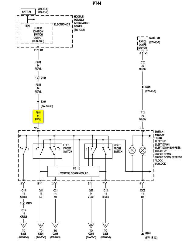
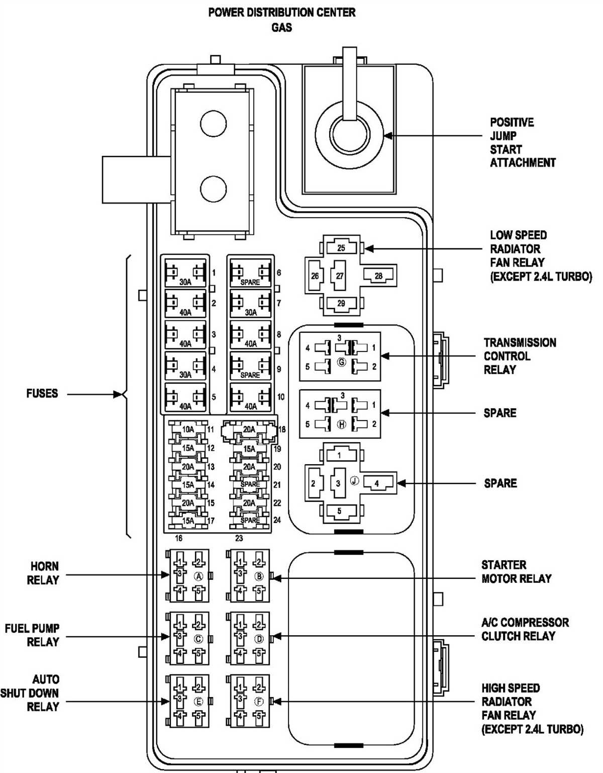
- Ignition switch and relay connections: The wiring diagram also includes the connections between the PCM, ignition switch, and relays. These connections are essential for controlling the power supply to the PCM and other components.
The wiring diagram for the 2006 PT Cruiser PCM provides a detailed overview of the electrical connections involved in the PCM’s operation. It helps technicians and mechanics diagnose and troubleshoot any issues related to the PCM or its connected components. By understanding the wiring diagram, they can identify faulty connections, damaged wires, or malfunctioning components, and take appropriate actions to resolve the problems.
PCM Wiring Diagram Sections
The PCM (Powertrain Control Module) wiring diagram for a 2006 PT Cruiser is divided into different sections to represent the various components and circuits involved in the vehicle’s engine control system. These sections provide a detailed overview of the electrical connections and wiring paths that allow the PCM to communicate and control various engine functions.
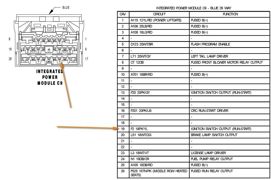
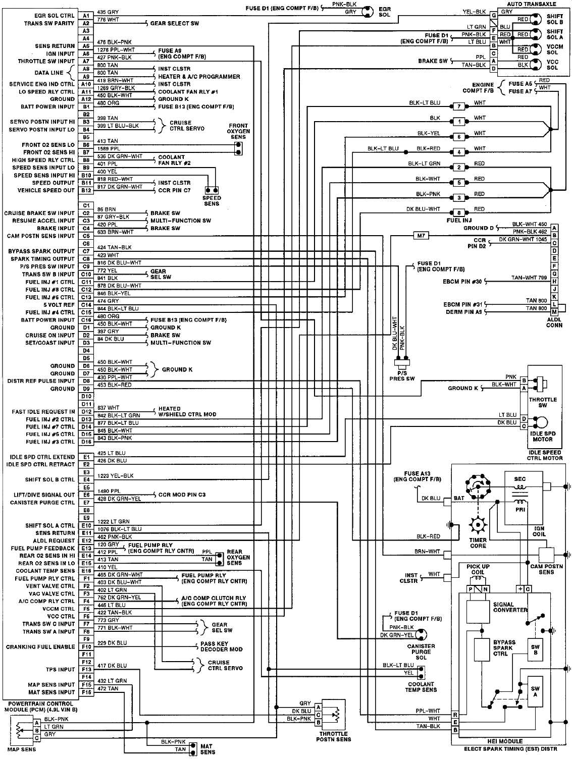
Main PCM Connector
The main PCM connector section includes a diagram of the connector pinouts, indicating the specific wires and their corresponding functions. This section is crucial for understanding the different signals and sensors that are connected to the PCM, such as the crankshaft position sensor, camshaft position sensor, throttle position sensor, and more.
Sensor Circuits
The sensor circuits section of the PCM wiring diagram focuses on the wiring connections between the different sensors in the engine and the PCM. This includes sensors like the coolant temperature sensor, intake air temperature sensor, MAP (Manifold Absolute Pressure) sensor, and oxygen sensors. Understanding this section is essential when troubleshooting sensor-related issues or diagnosing problems with the engine’s fuel and ignition systems.
Actuator Circuits
The actuator circuits section shows the wiring connections between the PCM and various actuators that help control engine functions. This includes components like the fuel injectors, ignition coils, idle air control valve, and EVAP (Evaporative Emission) system solenoids. This section is valuable when diagnosing issues related to engine misfires, rough idle, or problems with the fuel delivery system.
Power and Ground Circuits
The power and ground circuits section is dedicated to illustrating the electrical connections that supply power and ground to the PCM. This includes the main power source, such as the battery, as well as the grounding points for the PCM. Understanding the power and ground circuits is essential for diagnosing issues related to a lack of power or faulty grounds, which can cause various engine performance problems.
PCM Connector Views
This section provides views of the PCM connectors, indicating the different pins and their locations within the connector. These views are helpful when physically inspecting the PCM connectors or when trying to identify a specific pin for testing or troubleshooting purposes. The views can also provide information on the connector layout and orientation, allowing for easier identification and connection of wires during repairs or modifications.
Overall, the PCM wiring diagram sections provide a comprehensive overview of the electrical connections and wiring paths within the 2006 PT Cruiser’s engine control system. Understanding these sections is essential for diagnosing and troubleshooting engine-related issues and ensuring proper electrical connections are maintained.
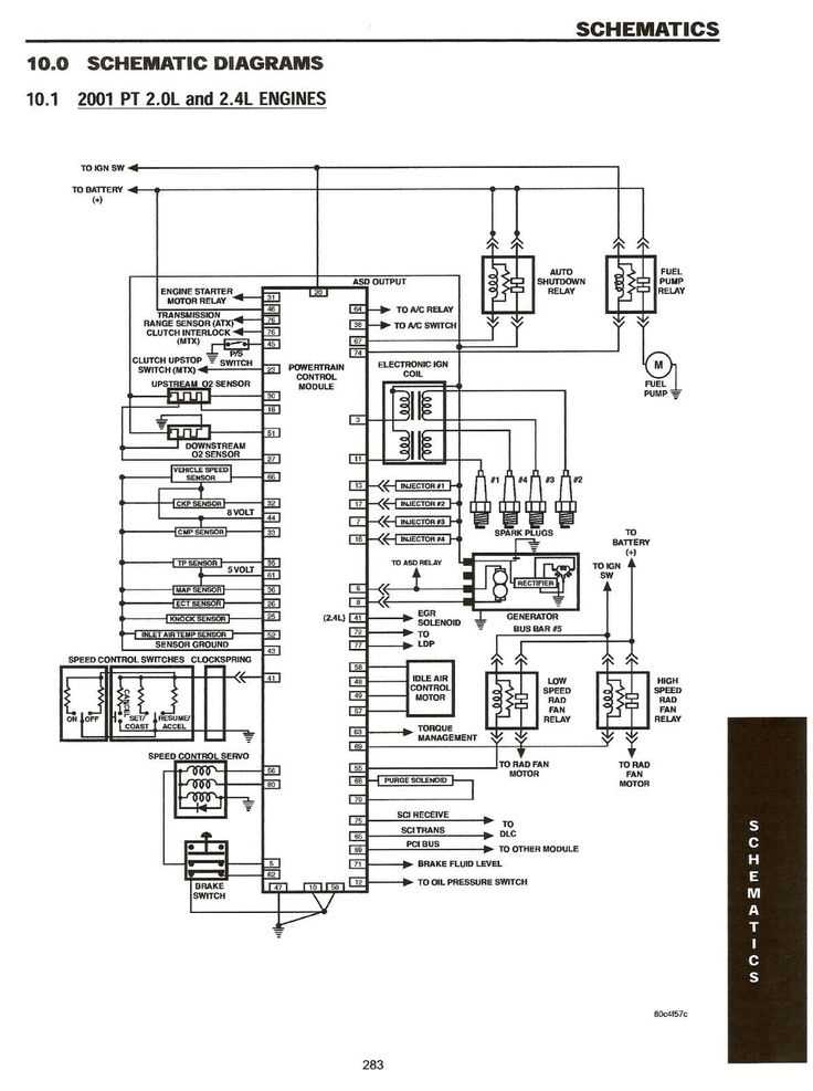
Breakdown of the sections of the PCM wiring diagram
The PCM wiring diagram for a 2006 PT Cruiser is a detailed diagram that illustrates the connections and electrical components of the Powertrain Control Module (PCM) system. The diagram provides a visual representation of how the PCM interacts with various sensors, actuators, and other electrical components in the vehicle.
1. Power Supply Section

The power supply section of the PCM wiring diagram shows the connections and components that provide power to the PCM. This includes the battery, ignition switch, fuses, and relays. It is essential for ensuring that the PCM receives a constant and reliable power supply.
2. Ground Section
The ground section of the PCM wiring diagram illustrates the connections and components that provide a grounding path for the PCM. Grounding is crucial for the proper operation of the PCM and ensures that electrical currents have a path to dissipate. Ground connections may include engine grounds, chassis grounds, and specific ground points for the PCM.
3. Sensor Inputs Section
The sensor inputs section of the PCM wiring diagram displays the connections and components that connect various sensors to the PCM. These sensors include oxygen sensors, crankshaft position sensors, camshaft position sensors, and many others. Sensor inputs provide crucial data to the PCM, allowing it to make decisions and adjust vehicle parameters accordingly.
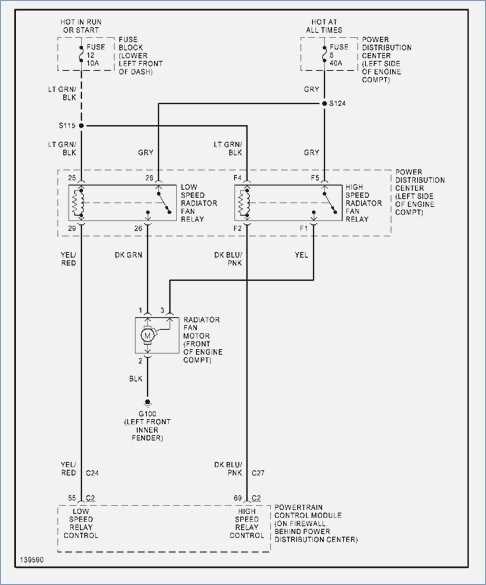
4. Actuator Outputs Section
The actuator outputs section of the PCM wiring diagram shows the connections and components that connect the PCM to various actuators in the vehicle. These actuators include fuel injectors, ignition coils, cooling fan relays, and others. Actuator outputs allow the PCM to control and adjust the operation of these components, optimizing engine performance and emissions.
5. Communication Section
The communication section of the PCM wiring diagram illustrates the connections and components that enable communication between the PCM and other electronic control modules in the vehicle. This may include the transmission control module, body control module, or anti-lock brake control module. Communication between modules is crucial for integrated vehicle operation and diagnostics.
Conclusion
The PCM wiring diagram is a comprehensive visual representation of the electrical connections and components of the PCM system in a 2006 PT Cruiser. It breaks down the wiring into specific sections, including power supply, ground, sensor inputs, actuator outputs, and communication. Understanding and interpreting the PCM wiring diagram is essential for diagnosing and troubleshooting electrical issues in the vehicle.
Q&A:
What is a PCM wiring diagram?
A PCM wiring diagram is a detailed representation of the wiring and connections between the Powertrain Control Module (PCM) and various components in a vehicle’s electrical system.
What does the PCM control?
The PCM controls various aspects of the vehicle’s powertrain, including the engine, transmission, and emissions systems. It monitors various sensors and actuators to ensure proper operation and performance.
What are the sections in a PCM wiring diagram?
A PCM wiring diagram typically includes sections for the power supply, ground connections, sensor inputs, actuator outputs, and communication lines. These sections provide a comprehensive overview of the electrical connections in the PCM circuit.
Why is a PCM wiring diagram important?
A PCM wiring diagram is important for troubleshooting electrical issues in a vehicle. It helps technicians identify and diagnose problems by providing a visual representation of the wiring connections and the flow of electrical signals in the system.
What information can be found in a PCM wiring diagram?
A PCM wiring diagram typically includes information about the wire colors, connector pinouts, circuit paths, and component locations. It also provides information on the types of sensors and actuators connected to the PCM.