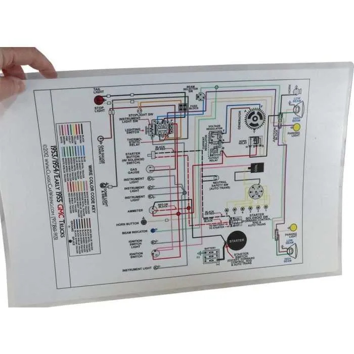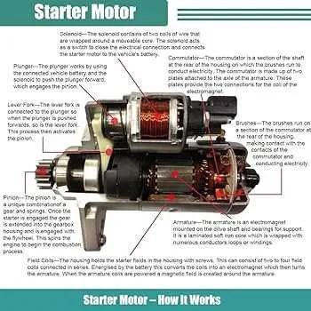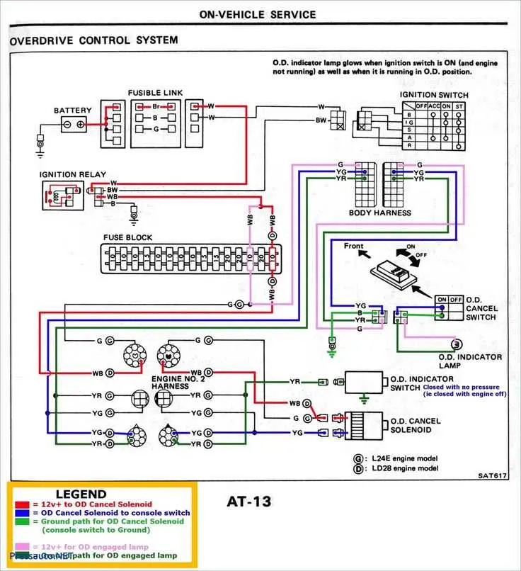
If you’re troubleshooting or replacing the ignition system components in a vehicle with a two-wire configuration, it’s crucial to focus on the precise connection points to ensure proper functionality. The first wire is typically responsible for providing power directly from the ignition switch to the relay, while the second serves as the ground or activation signal for the starter mechanism.
Power Supply Connection: The power wire should be connected directly from the ignition switch to the terminal on the solenoid, which then distributes voltage to engage the starter motor. Be sure that this wire is securely fastened and free of corrosion or fraying, as these issues can prevent sufficient current flow and lead to system malfunctions.
Activation Circuit: The activation signal, often the second wire, triggers the solenoid by completing the ground path. It’s important that this wire maintains a clear connection to the ground point, usually through the vehicle’s chassis or an isolated ground terminal. A poor connection here can cause intermittent starting issues.
Check the integrity of both connections before attempting to power up the system. Any signs of wear or improper connection could result in failure to start or damage to other critical components in the ignition system.
Starting System Electrical Connection Guide

To correctly set up the electrical connections for the starting system, focus on the two primary connections: the ignition signal and the battery feed. These two lines control the operation of the motor and need to be securely fastened and properly insulated.
Ensure the ignition circuit is connected to the solenoid’s activation terminal. This circuit should carry the signal when the key is turned to the “start” position. The battery feed must be connected directly to the motor terminal of the solenoid for consistent power supply.
Verify that both connections are free from corrosion and secured tightly to avoid intermittent starts or total failure of the system. If any damage is found in the terminals, replace the corroded parts immediately.
For an accurate understanding of the connections, refer to the following table outlining the two key terminals and their respective functions:
| Terminal | Connection Type | Function |
|---|---|---|
| Ignition Signal | Small Gauge | Activates solenoid when the key is in the “start” position |
| Battery Feed | Large Gauge | Delivers power from the battery to the motor |
Proper alignment and wiring of these connections ensure the motor gets power when needed, preventing unnecessary wear on the electrical components. Check these connections during regular maintenance to ensure reliable performance.
Understanding the 2-Wire Starter System in 2007 Chevy Malibu

The two-wire ignition system in this vehicle is straightforward yet crucial for starting the engine. The first wire connects the solenoid to the battery, delivering the necessary power. The second wire links the ignition switch to the solenoid, acting as the signal to engage the motor. It’s essential that both connections are secure to avoid starting issues.
If you’re troubleshooting starting problems, start by checking the integrity of these two circuits. Use a multimeter to ensure there’s continuity between the battery and the solenoid, as well as from the ignition switch to the solenoid. A common issue could be a loose or corroded connection that interrupts the signal or power flow.
For proper diagnosis, start by confirming the voltage at both ends of each wire. If there’s no voltage on the signal wire when the ignition is turned, the issue likely lies with the switch or the wire itself. If power is present but the solenoid doesn’t activate, you may have a fault in the solenoid or motor.
Inspect the connectors for any signs of wear or corrosion. If necessary, clean the terminals and check the cables for any visible damage. Ensure all connections are tightly fitted to avoid intermittent starting failures.
If replacing components, ensure you match the solenoid’s specifications to ensure compatibility. Always use high-quality parts to prevent further issues down the road.
How to Identify the Correct Wires for the Starter Circuit
Start by locating the solenoid, as it typically has two main terminals. The larger terminal is where the positive cable from the battery connects, and the smaller terminal is where the activation signal comes from the ignition switch. Use a multimeter to test the voltage on the smaller terminal when the ignition is turned to the start position. This terminal should show 12V when engaged.
Next, identify the ground connection. This is usually a direct link from the chassis to the negative terminal of the battery or the engine block. Make sure it is free from corrosion and securely attached to ensure proper grounding for the circuit.
The next step is checking the continuity between the solenoid and the motor. Using a continuity tester, ensure that the signal from the ignition switch is properly reaching the solenoid. If there’s no continuity, you may need to check the ignition switch or replace the relay if one is involved in the circuit.
Finally, verify the connections on the fuse block or relay. Ensure that all fuses and relays related to the ignition circuit are intact and functioning properly. If the circuit has a dedicated relay, check the relay coil and contacts for any damage or wear.
Troubleshooting Common Electrical Issues in the Starter Circuit
If the engine won’t start, it’s crucial to check the electrical connections involved in the starting system. Follow these steps to identify and resolve common problems:
- Check Battery Voltage: Ensure the battery has sufficient voltage, ideally around 12.6V. A weak battery can cause a lack of power to the system.
- Inspect the Solenoid: The solenoid can fail due to wear or corrosion. Test the solenoid for continuity, and if it’s faulty, it will need to be replaced.
- Examine the Connections: Loose or corroded terminals can impede proper electrical flow. Clean the terminals and ensure they are tightly connected.
- Test the Relay: A malfunctioning relay can prevent the current from reaching the starter. Test the relay with a multimeter to verify if it’s functioning properly.
- Check the Ignition Switch: The ignition switch must complete the circuit to engage the starter. A failed switch will prevent the engine from cranking.
- Inspect the Ground Connection: A poor ground can result in intermittent starting issues. Clean the ground strap and make sure it’s securely attached to both the frame and the engine block.
- Test the Safety Neutral Switch: If the vehicle is not in “Park” or “Neutral,” the safety switch will prevent starting. Ensure the vehicle is in the correct position and the switch is functioning.
Start with the simplest checks first and work your way through the system. Identifying the root cause of the issue quickly can save both time and money.