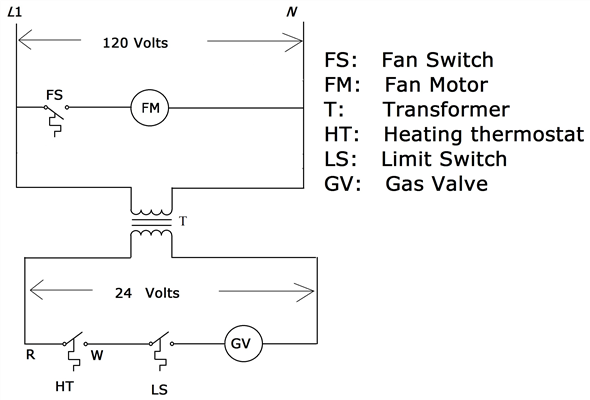
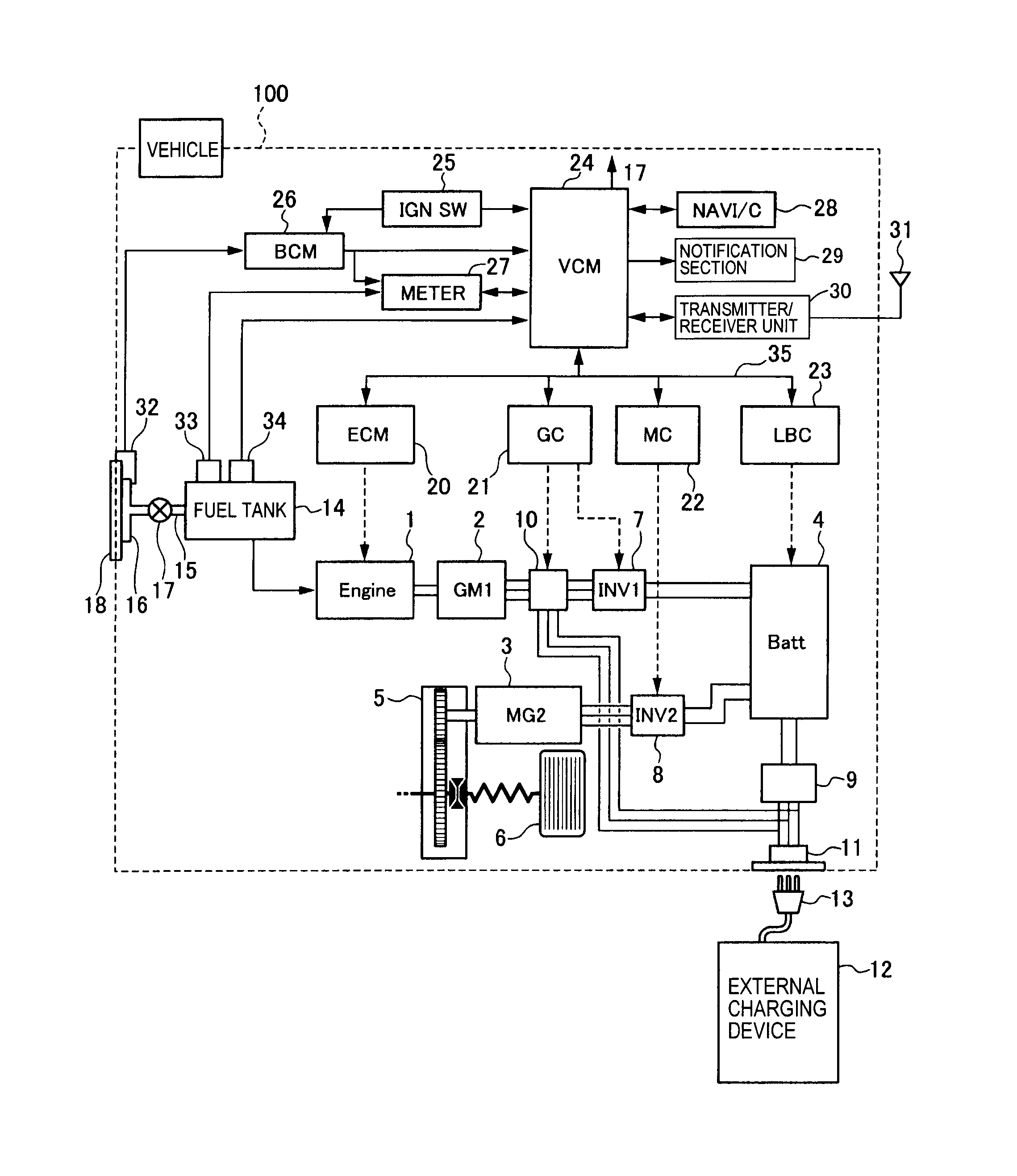
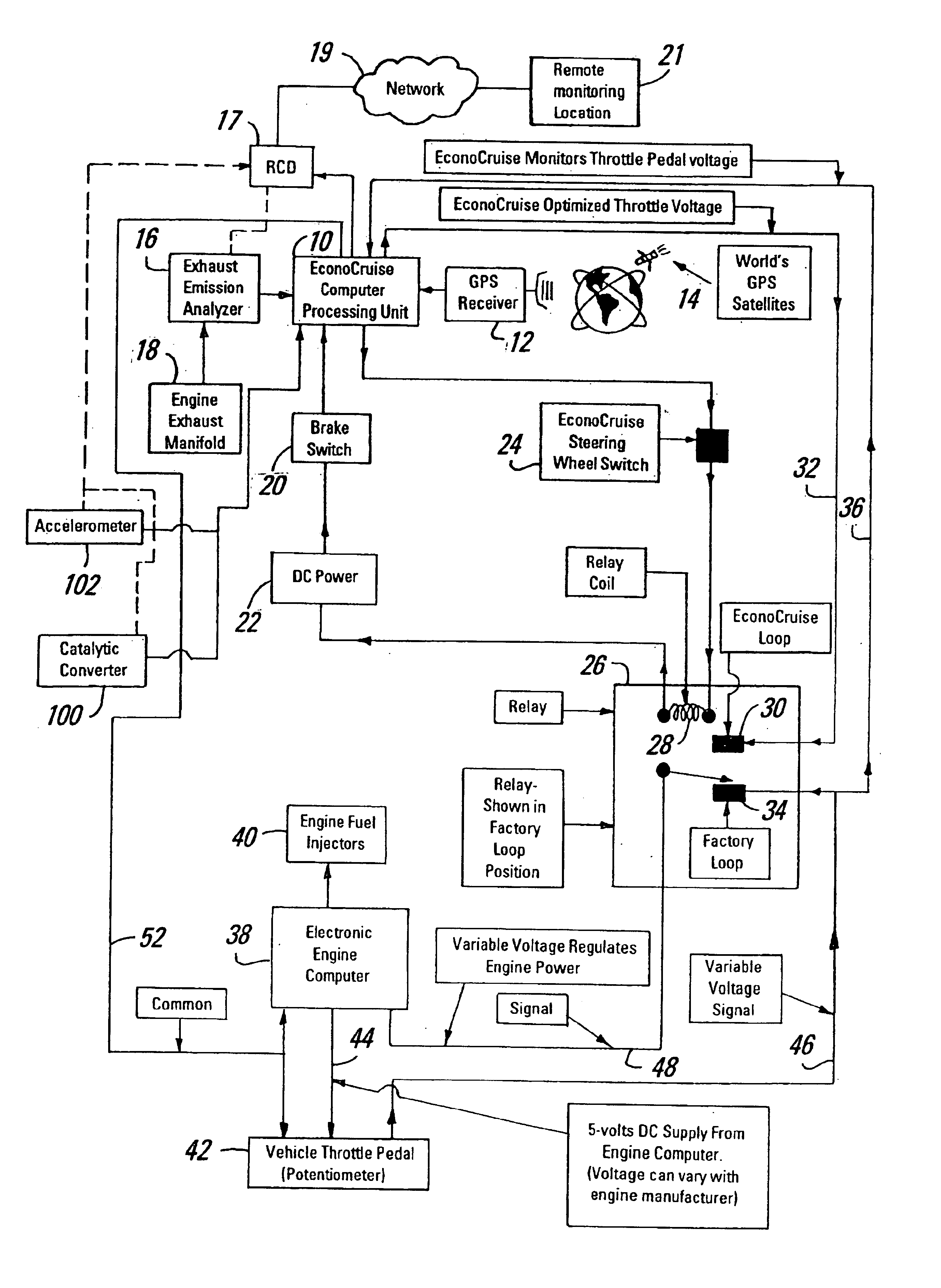
Figure Variable Engine Speed Control Schematic using Remote Engine Speed Controller.
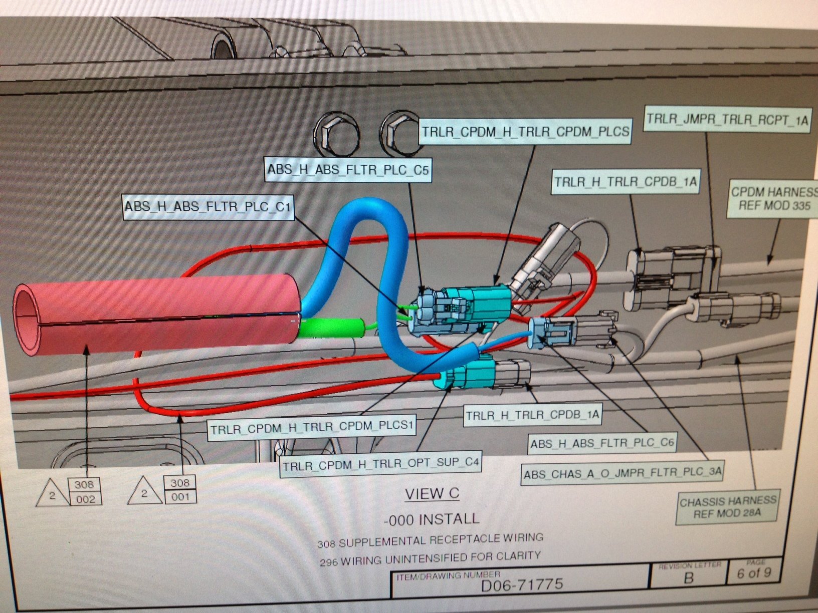
. Table Accelerator Pedal Sensor Wire Colors and Signals. International, Maxxforce, Cummins and Isuzu engines, Diagnostic and electrical APS/IVS Accelerator position signal in range DTC APS/IVS Install the 5 wire breakout tee between the APS/IVS sensor and harness connector.
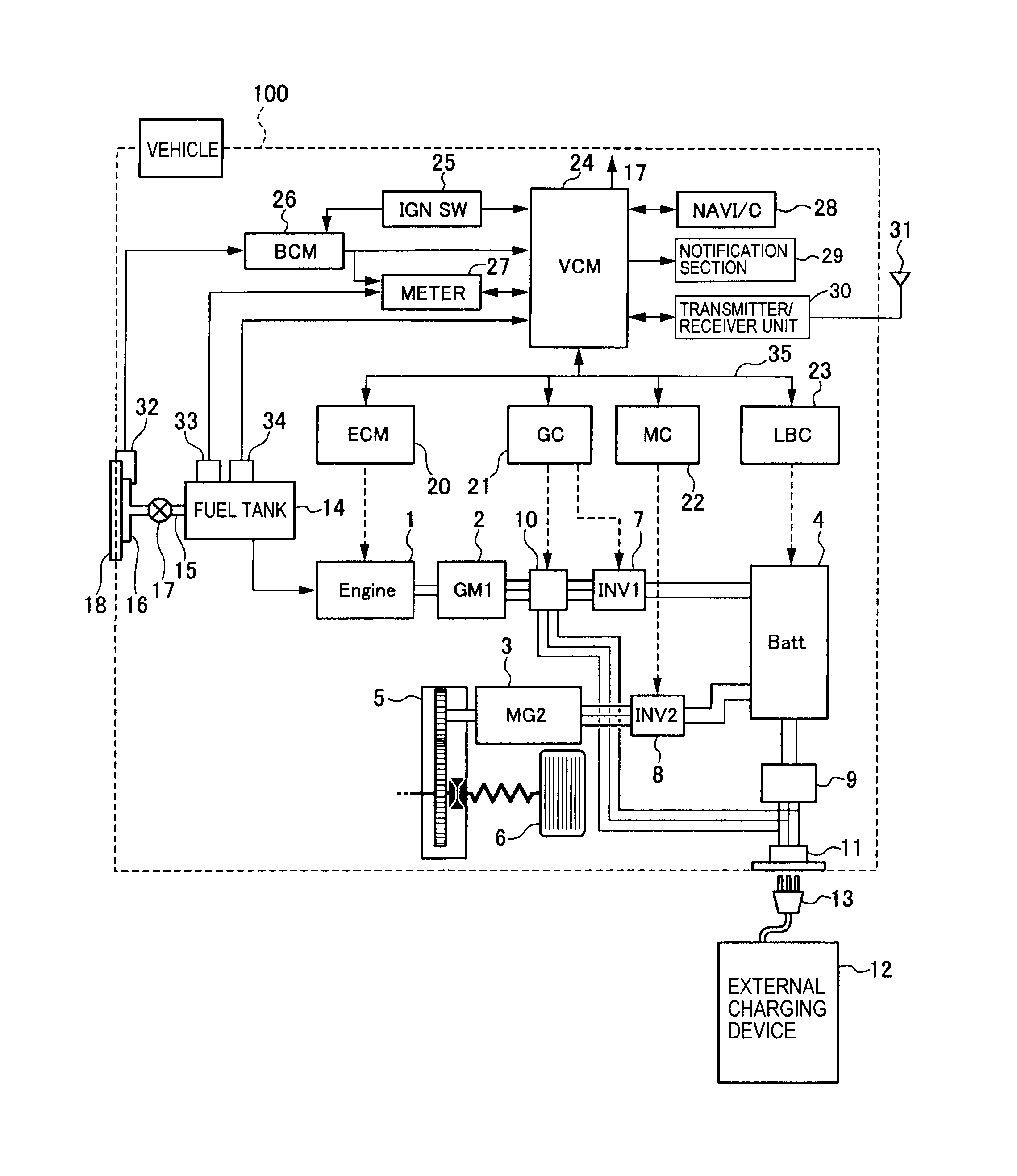
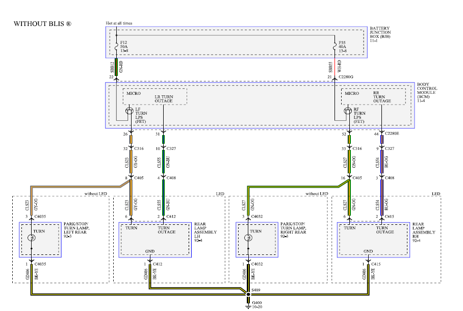
. IH 1HTMMAAN9CH, Last week there was a code. Electrical Circuit Diagrams.
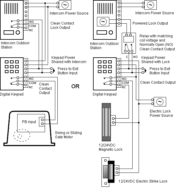
ProStar® and LoneStar® – Models Built June 14, and After. Engine Family: MaxxForce® 11, 13, and 15L. See SD for Standard and Premium Controllers.
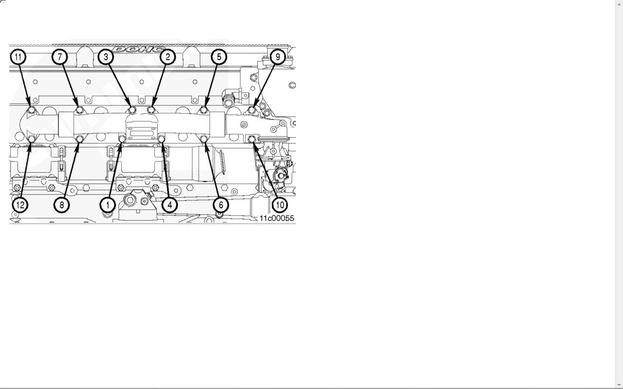
FIGURE 1 – EC™ . All wire harness connectors must be properly seated. The use of secondary.
for last one month i have that problem on my Columbia The engine starts fine the problem is that throttle pedal doesn’t accelerate some.Feb 16, · throttle loss Discussion in ‘International Forum’ started by sul, Feb 10, Feb 10 There is something wrong with the pedal sensor or related wiring. Throttle position sensor faults cause the engine to idle only and set a “Stop” engine light. SID-4 fmi 4 prostar maxxforce q posted Nov 20, Speedo and Tach working.

Maxxforce DT 9 10 Wiring Diagram. Diagrama de Arneses DDEC. MAXXFORCE 11 and 13 Beginning with Model Year R 1 Camshaft Position (CMP) 3 6 1 5 1 4 Documents Similar To Maxxforce Electronic Control System Diagnostic.
Maxforce Ingles. Uploaded by. Ginna Quin.
Navistar O & M Manual. Uploaded by.5/5(1). Maxxforce DT 9 10 Wiring Diagram.
Codigos Camiones International. ipipdf. Proustpdf.
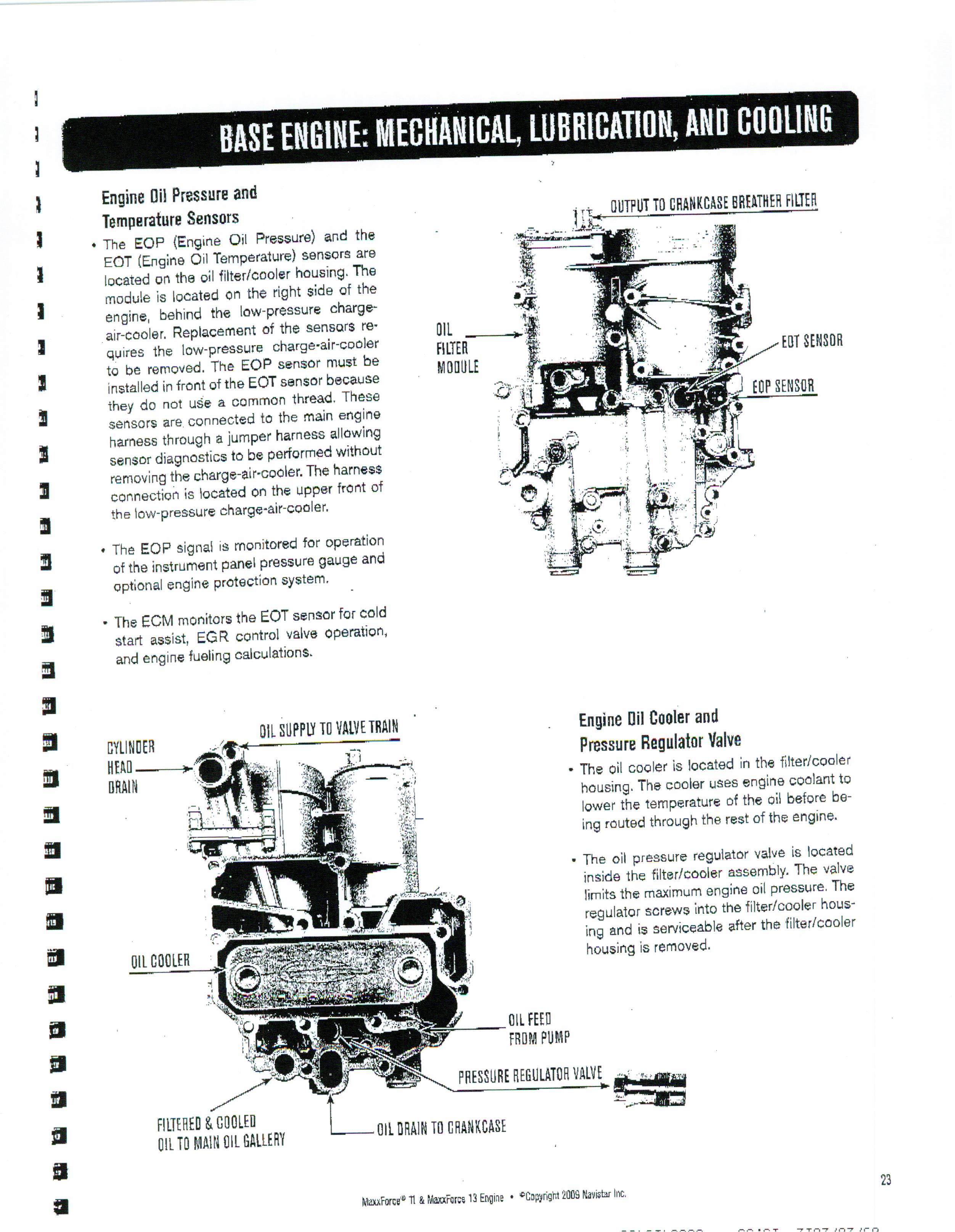
MAXXFORCE 11 and 13 Beginning with Model Year R 1 Camshaft Position (CMP) 3 6 1 5 1 4 Documentos similares a Maxxforce Electronic Control System Diagnostic. Advanced EGR vs SCR.
Cargado por. Hannu Jaaskelainen.
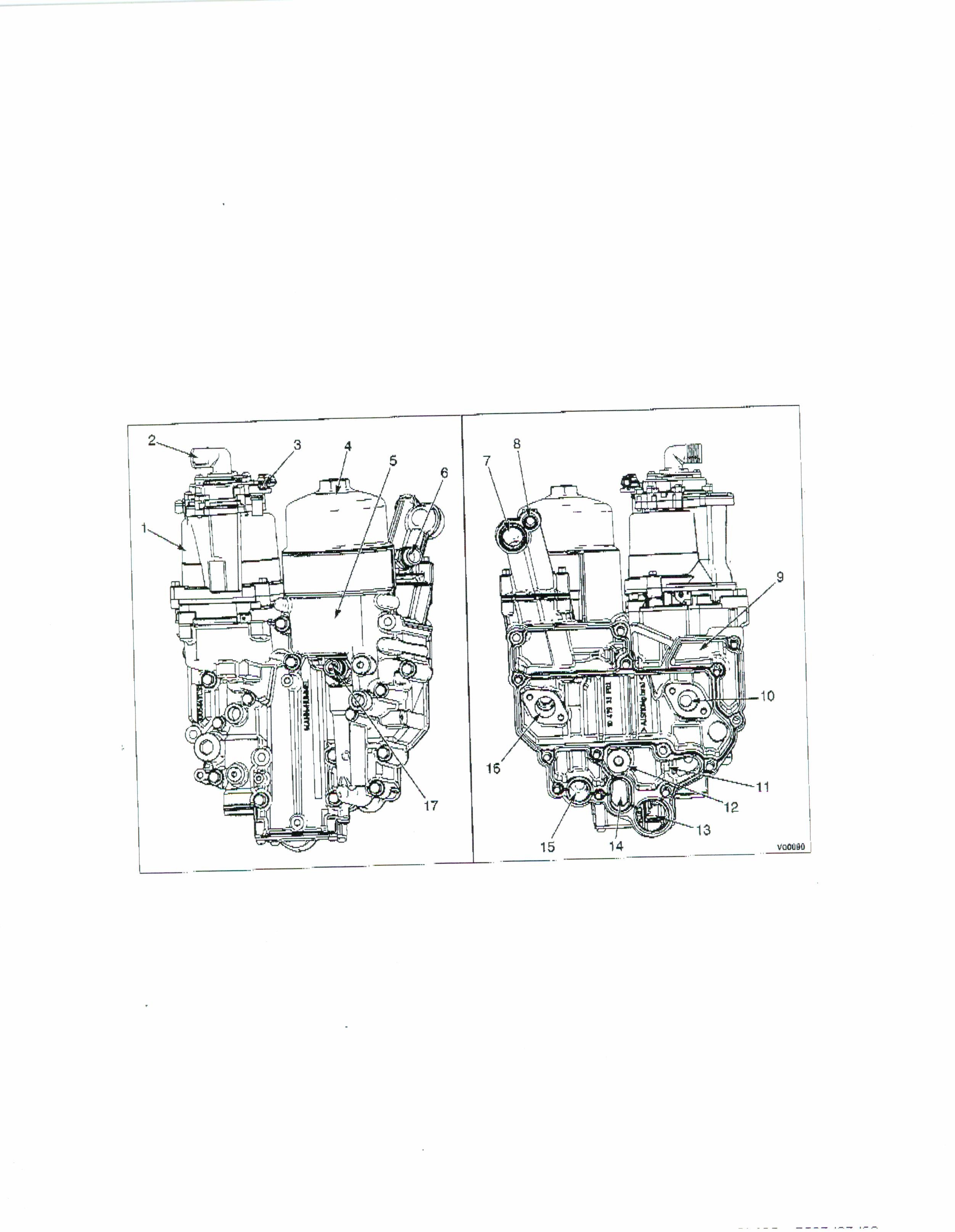
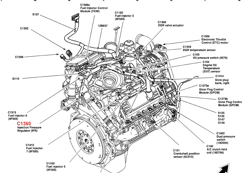
2 ® MaxxForce 11 and MaxxForce® 13 Engine Training Program The front gear train is located behind the front cover. The gear train drives the oil pump, low-mount cooling fan, and the accessory drive assembly. The fuel filter module and high-pressure fuel pump are located on the left side of the engine.
The pump is capable of. Check out International PROSTAR Cab Parts for sale.
We help you find the heavy duty truck parts that you need. INTERNATIONAL PROSTAR CAB WIRED FOR INTERNATIONAL MAXXFORCE 13 Call the following number for the part.
International PROSTAR (Stock #IHC) Cab & Cab Parts / Cabs.throttle pedal problem | schematron.org Trucking Forum | #1 CDL Truck Driver Message BoardNavistar Maxxforce 9 10 Inlet Intake Throttle Valve | eBay