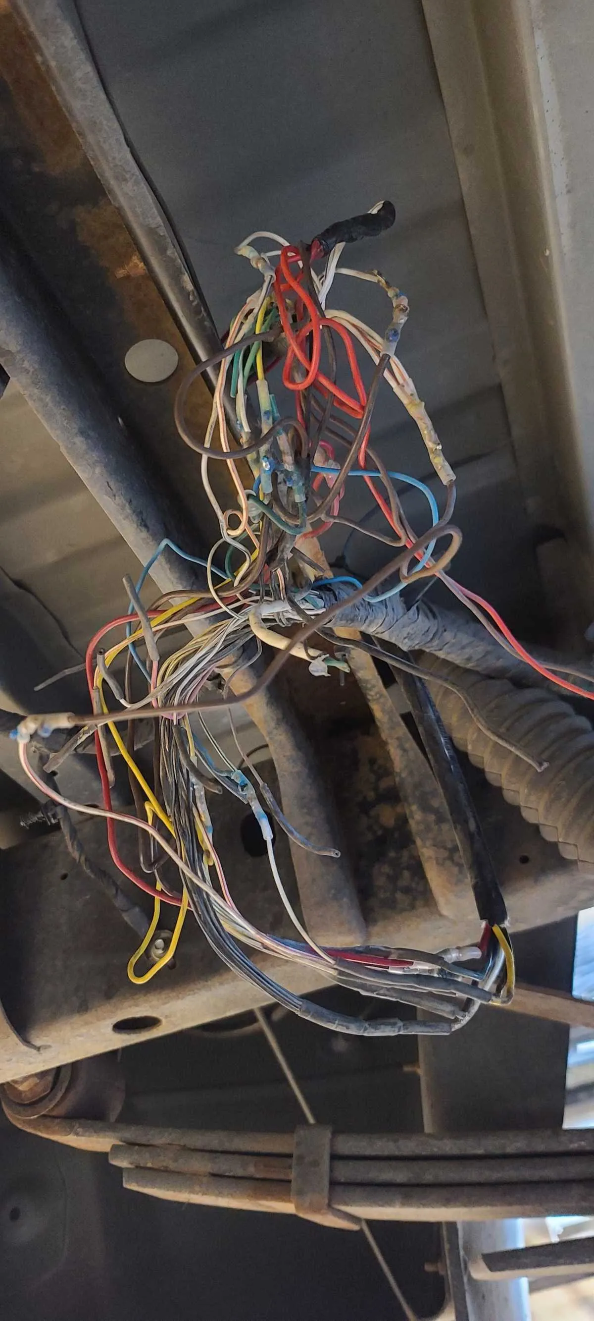
To ensure proper installation of the rear lamp system on your vehicle, follow these wiring steps. First, check the connection points on both the left and right assemblies. These typically consist of a multi-pin connector for power, ground, and signal wires. Make sure to confirm each wire’s function before making any connections.
Key Points to Verify: Ensure that the power lead is connected to the designated terminal, while the ground wire is properly linked to a clean metal surface. Double-check the signal wires for brake and turn indicator functionality. Always use the manufacturer’s recommended wire gauge to avoid power loss.
Common Issues: If you experience malfunctioning lights, inspect the connectors for corrosion or loose connections. Replace any worn-out or damaged wires immediately to avoid further electrical problems.
Electrical Connector Configuration for Tail Lamp System
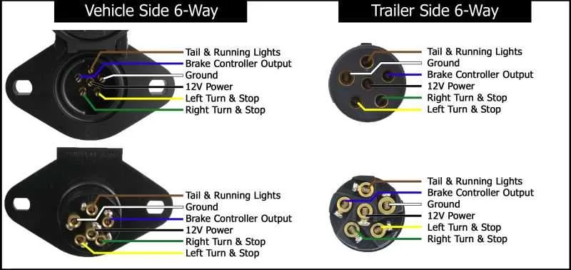
Ensure correct connections when linking the back-end illumination components. The assembly uses a multi-pin connector, where each terminal corresponds to a specific function. The following guide outlines the key pin assignments for seamless installation and troubleshooting:
Pin 1: Ground. Connect this pin to the vehicle’s chassis for proper grounding.
Pin 2: Brake lights. This wire controls the brake signal, which should be linked to the appropriate circuit to activate the brake lamps.
Pin 3: Turn signal left. Attach this pin to the left indicator system, ensuring proper signaling on the left side.
Pin 4: Turn signal right. Link this terminal to the right turn signal system for the intended right-side indication.
Pin 5: Tail lights. Connect this pin to the rear running lights for standard illumination when the vehicle is in motion or parked.
Pin 6: Reverse lights. For the backup light circuit, this pin should trigger the reverse lamps when the vehicle is shifted into reverse gear.
Check the wiring integrity and confirm that each connector is securely fastened before activation. Use a multimeter to test voltage levels and ensure no short circuits are present. Proper isolation of power and ground circuits is crucial to avoid potential electrical failures.
Identifying the Pin Configuration for Rear Lighting Connections
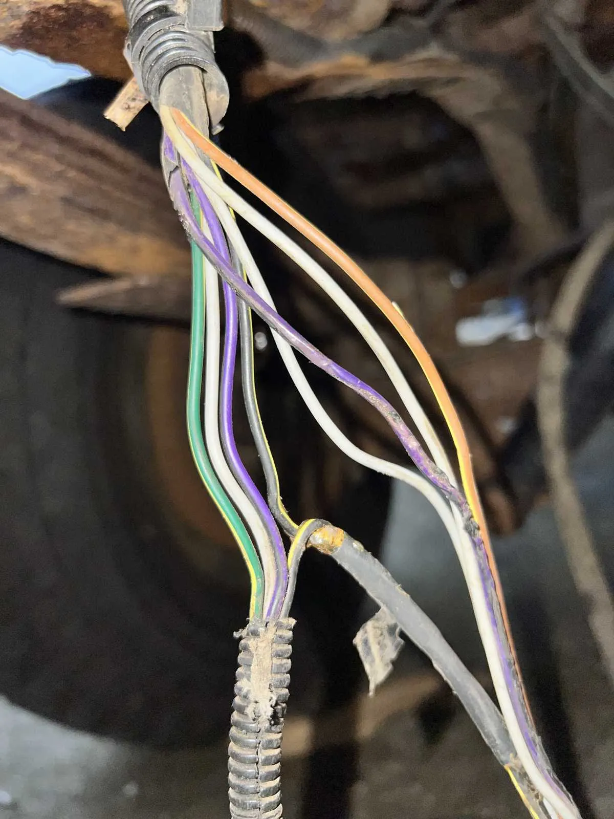
To determine the correct pin arrangement for the vehicle’s back-end electrical system, follow these steps:
- Start by locating the connector near the vehicle’s rear section, typically located near the tailgate or bumper area.
- Examine the number of pins available in the connector. Typically, these systems use a multi-pin setup, with specific pins designated for functions like brake lights, turn signals, and ground connections.
- Refer to the manufacturer’s specifications or service manual to cross-reference each pin with its corresponding function.
Here’s a typical configuration:
- Pin 1: Ground – Often the first pin in the connector, used to complete the electrical circuit.
- Pin 2: Left Turn Signal – Controls the left side indicator.
- Pin 3: Right Turn Signal – Controls the right side indicator.
- Pin 4: Brake Light – Activates the brake lights when the pedal is pressed.
- Pin 5: Reverse Light – Illuminates when the vehicle is in reverse gear.
- Pin 6: Running Lights – Ensures the rear illumination is on for night driving.
By confirming the specific pin assignments, you ensure proper functionality and avoid electrical malfunctions. Always use a multimeter to check for voltage continuity across each pin to verify connections.
How to Troubleshoot Common Electrical Issues in Tail Lamp Circuits
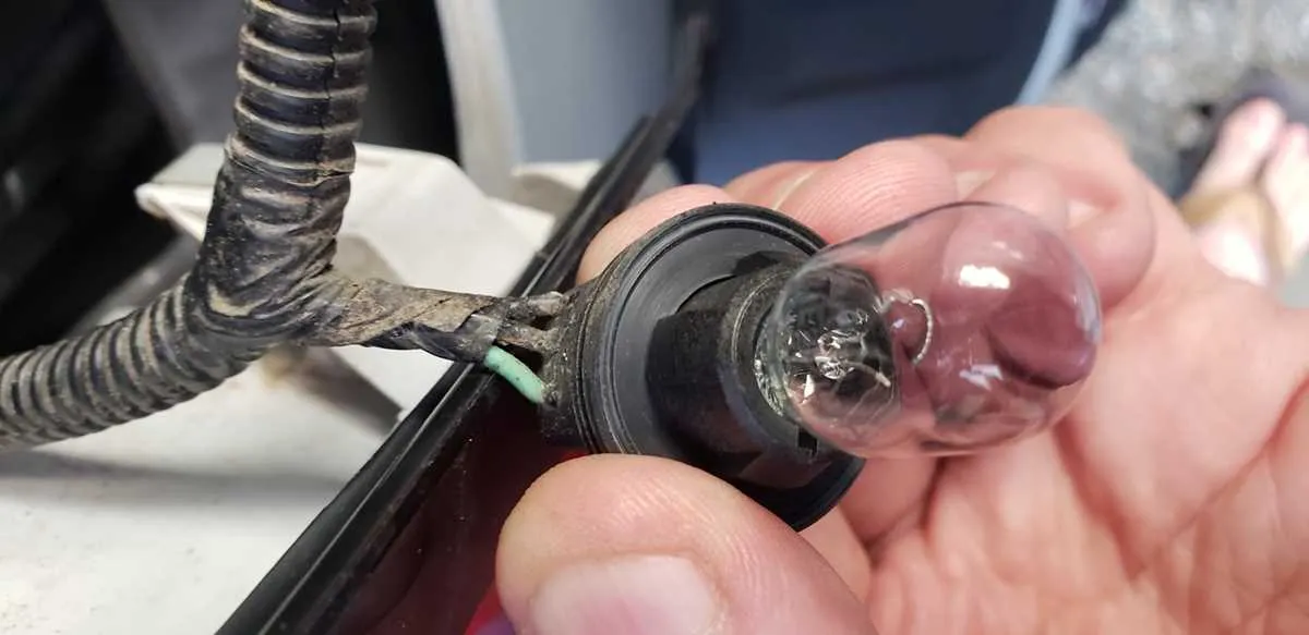
Start by inspecting the fuses related to the tail lamp circuit. If a fuse is blown, replace it with one of the correct amperage. Always verify the condition of the fuse using a multimeter to ensure continuity. If the fuse blows again after replacement, the issue lies within the circuit, and further investigation is needed.
Next, check the bulb sockets. Corrosion or loose connections in the socket can cause intermittent or complete failure of the lamps. Clean the contacts thoroughly and ensure a tight fit. For stubborn corrosion, use a contact cleaner and reassemble the socket carefully.
Verify the integrity of the ground connection. A poor or missing ground can lead to malfunctions in the entire system. Use a multimeter to test continuity between the ground wire and the vehicle’s chassis. Clean any rust or dirt from the grounding point and reattach the wire securely.
Examine the connectors and harnesses for signs of wear, pinched wires, or exposed cables. Pay close attention to the insulation, and if you find any damage, repair or replace the affected parts. A common issue is frayed wires where they bend or rub against other components.
If the signal is weak or non-functional, inspect the relay controlling the lamps. Relays can wear out over time and fail to activate the circuit. Test the relay by switching it with another one of the same type, or use a multimeter to check for proper activation when the circuit is engaged.
For more complex problems, consider tracing the entire electrical path using a circuit tester. Start at the fuse box and follow the wire to the tail light assembly. This process can reveal breaks, shorts, or faulty components that may not be immediately visible.
Lastly, check the vehicle’s control module if applicable. Some models use a central control unit to regulate various light circuits. Ensure the module is receiving and sending signals correctly. If the module is malfunctioning, it may need to be reprogrammed or replaced.
Step-by-Step Guide to Properly Connecting Tail Light Connectors
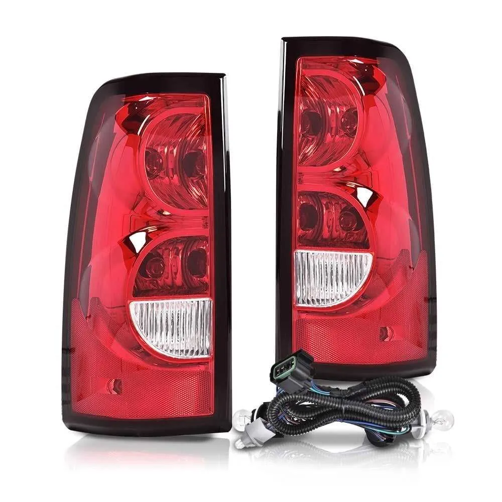
Ensure the correct installation of connectors for optimal performance and safety. Follow these precise steps for a smooth and error-free setup.
1. Identify the Correct Wiring Harness
Confirm that the wiring harness corresponds to the vehicle model and specific connector type. Mismatched harnesses can cause functionality issues or damage to the system.
2. Prepare the Connector Area
Clean the area where the connector will be mounted to avoid dirt or corrosion, which could compromise the connection. Use a dry cloth to wipe away any contaminants before installation.
3. Match the Wires to Their Terminals
Each wire in the harness must connect to the proper terminal in the connector. Refer to the terminal layout guide to ensure proper alignment.
4. Secure the Wires
Insert the wires into their respective terminals securely. Use a crimping tool to ensure each wire is firmly seated. A loose wire can lead to flickering or malfunctioning lights.
5. Test for Continuity
Once all connections are made, use a multimeter to test for continuity between the power source and the lights. This will confirm that the signal travels properly without interruptions.
6. Route and Secure the Harness
Ensure the harness is routed away from heat sources, sharp edges, or moving parts. Secure it with zip ties or clips to prevent abrasion or disconnections.
7. Final Inspection and Test
Before closing up, perform a final inspection of all connections. Turn on the vehicle’s electrical system to verify that all lights function as expected, including brake, turn signals, and reverse lights.
| Connection Type | Wire Color | Purpose |
|---|---|---|
| Brake Light | Red | Activates the brake light |
| Turn Signal | Yellow | Indicates a left or right turn |
| Reverse Light | White | Illuminates the area behind the vehicle when reversing |
| Ground | Black | Completes the electrical circuit |