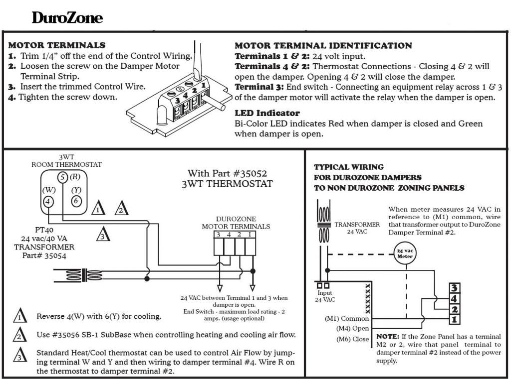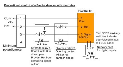
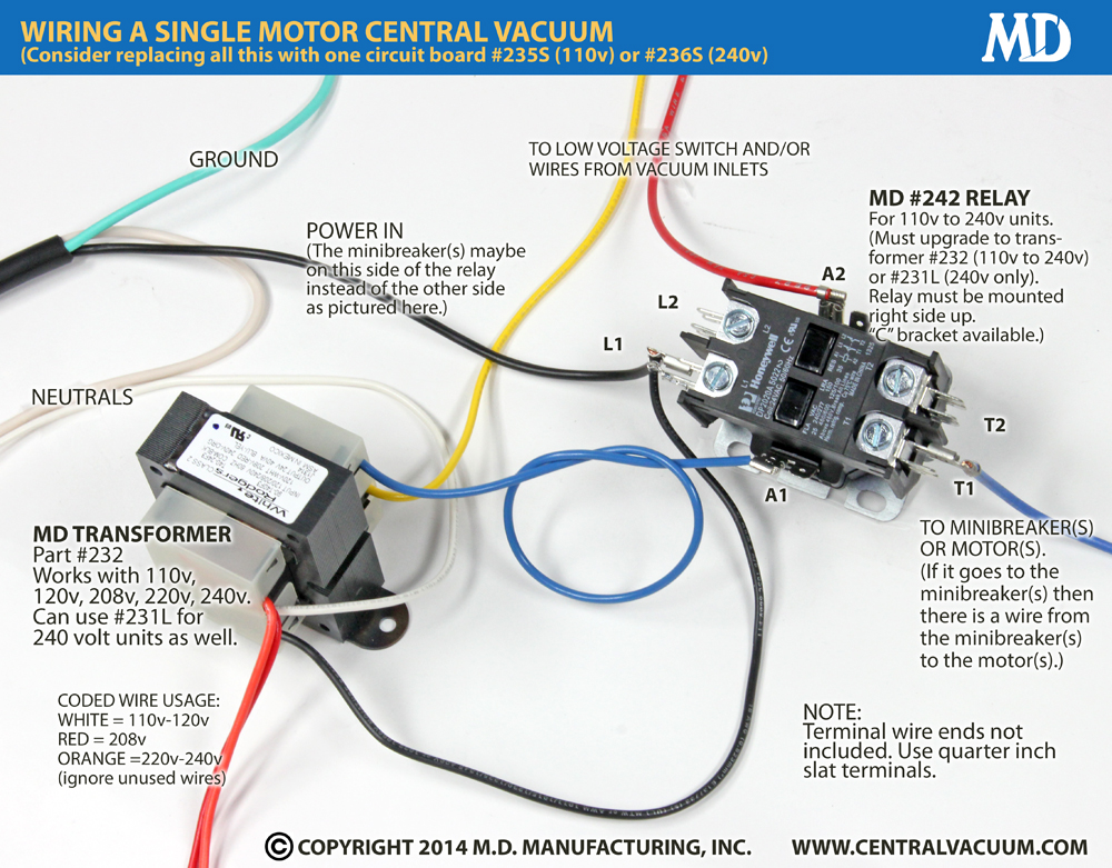
All FAMCO Round Motorized Dampers (without endswitch) are shipped with a flow control adjustment bold. Instructions include damper wire identification, and . Motorized.
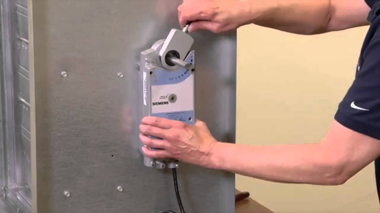
Damper. Ventilation.
Controller. Air.
Flow. Furnace/Air Handler .
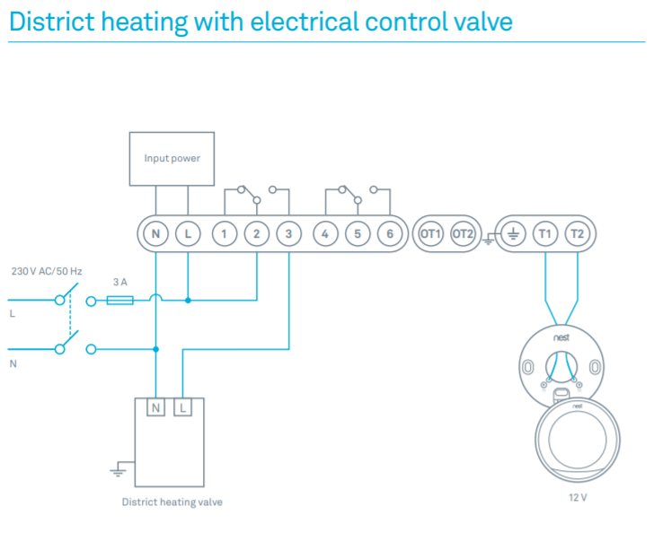
FIGURE 6 – OPTION 1 Wiring Connection Diagram 24 V TRANSFORMER .. A.
For system test be sure that 24 VAC is applied in series with the damper ( normally. MOTORIZED. FRESH AIR DAMPER.
MODEL. WGMFAD WGMFAD Manual: C.
Supersedes: The damper blade is powered by a VAC motor with spring return on power loss. The damper is powered. INTAKE DUCT AND MOTORIZED DAMPER Disconnect electrical power before wiring the FAVS to the equipment.
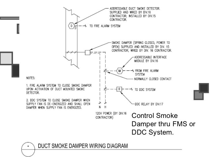
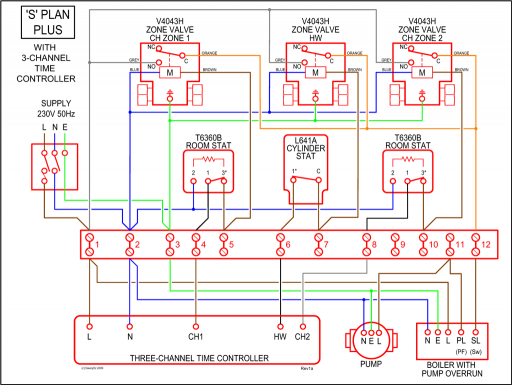
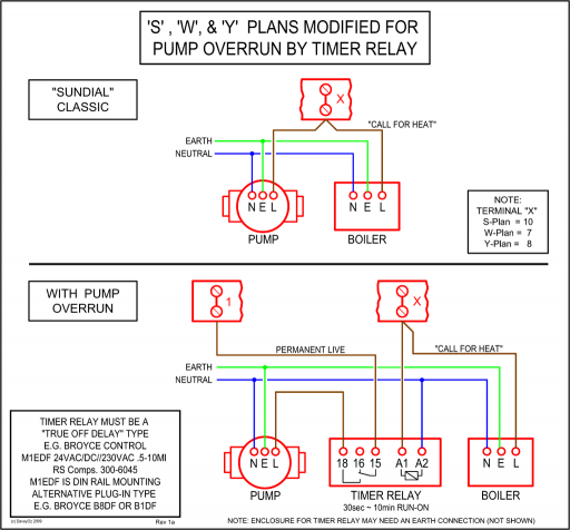
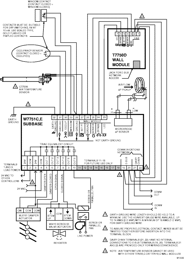
TYPICAL WIRING DIAGRAMS. 24V.
LINE. Installation, Operation, & Maintenance Manual.
2 TRION model TMD is a round damper with a 24 Vac, Motor Electrical Rating: 24 Vac, 60 Hz, 6VA.• motorized damper is 4 cfm/ft2 (see Table from ASHRAE Standard ) California Title 24 ( edition, section ) states that the dampers shall be certified in accordance with AMCA Publication to have a maximum leakage of 10 cfm/ft 2 at 1 in. wg. MS SERIES MULTI SIZE DAMPER.
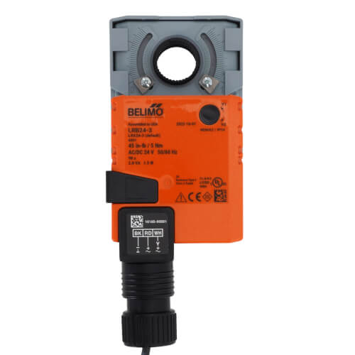
MOTOR TERMINALS. 1. Trim 1/4″ off the end of the Air Flow by jumping terminal W and Y and then wiring.
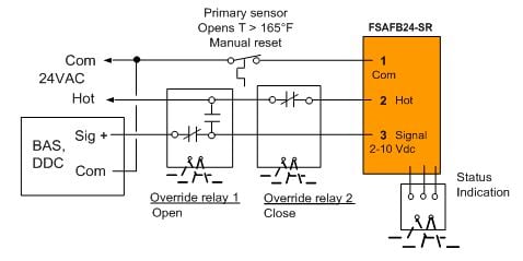
to damper terminal #4. Wire R on the thermostat to 24 VAC between Terminal 1 and 3 when damper is open.
End Switch – maximum load rating – 2 amps. (usage optional) TRANSFORMER.
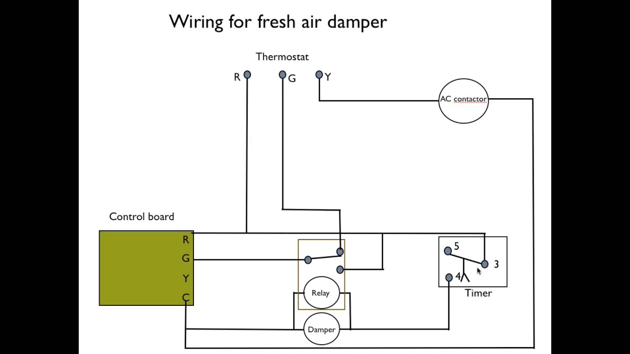
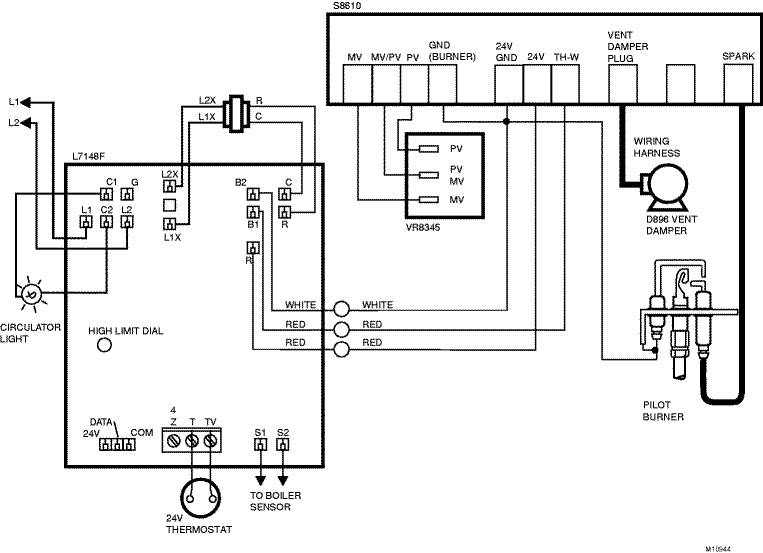
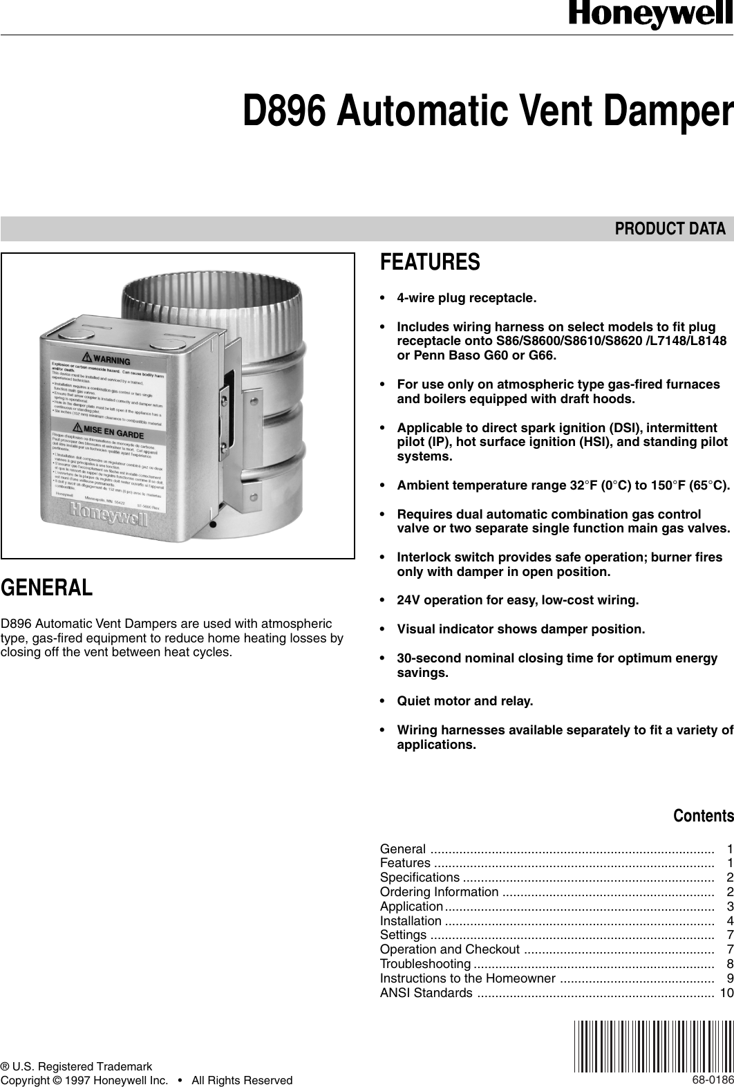
D Automatic Vent Damper APPLICATION The D Automatic Vent Damper is a 24 Vac, motorized stack damper. The damper closes off the furnace or boiler stack during the heating off-cycle. Use the D only on Wiring diagram for D connection to .

• motorized damper is 4 cfm/ft2 (see Table from ASHRAE Standard ) California Title 24 ( edition, section ) states that the dampers shall be certified in accordance with AMCA Publication to have a maximum leakage of 10 cfm/ft 2 at 1 in. wg.
Damper: Two gage galvanized steel plates locked together with an elastomeric gasket sandwiched between. Actuator: Internal actuator w/synchronous motor and gear reduction is direct coupled to the damper shaft. It has a drive time of 60 seconds.
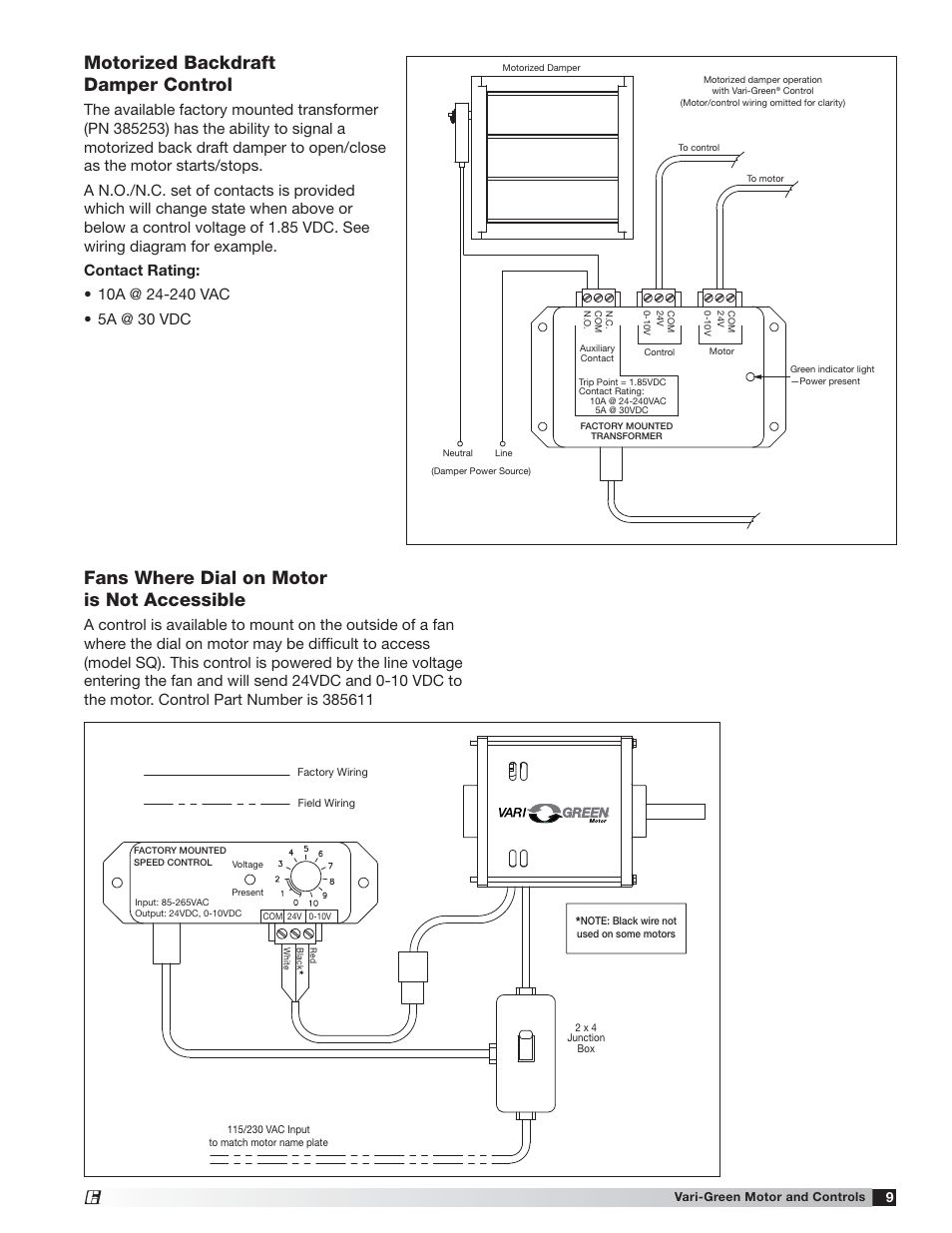
• Electrical Rating: † Power Supply—24 VAC (20 to 30 VAC) at 50/60 Hz.HOM – Combustion Air Damper – Installation InstructionsWiring Relay for Range hood Make-up Damper?? | All About Circuits
