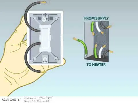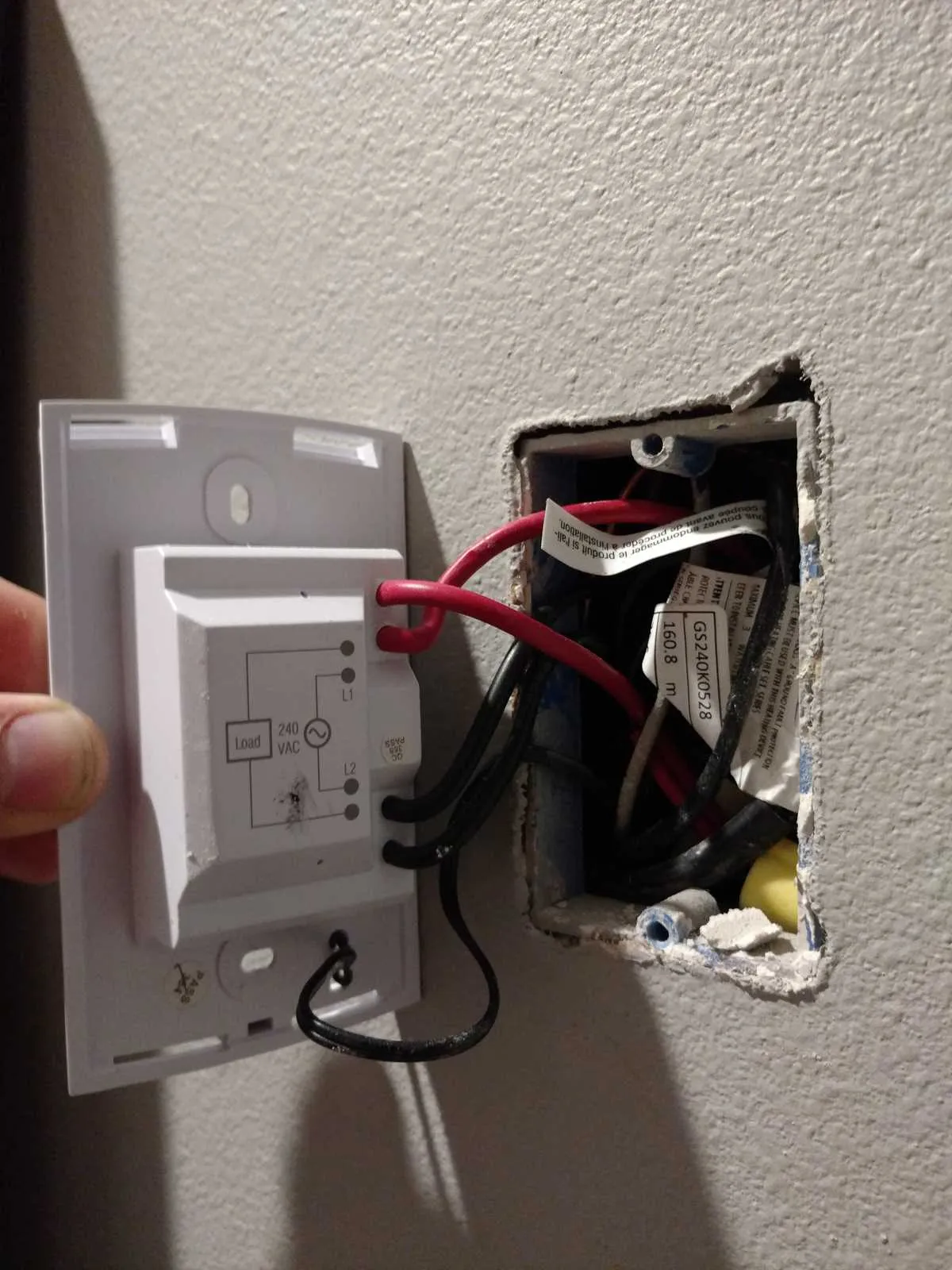
For optimal performance and safety, ensure that the power source is properly connected to the heating unit by using the correct gauge wire and circuit breakers. The main power line should match the requirements of the heater, which typically involves a dedicated 30-amp breaker and 10-gauge wire for most installations. Double-check the manufacturer’s specifications before proceeding.
When wiring, it’s crucial to connect the live and neutral wires correctly to prevent any electrical hazards. Typically, the live wire is connected to the brass terminal while the neutral is linked to the silver terminal. The ground wire should always be attached to the grounding screw, ensuring that the unit is properly grounded to avoid shocks.
If you are unsure about the amperage, it is better to overestimate than underestimate. Installing an appropriately rated circuit breaker is a key step in preventing overloads and fires. Always inspect the wiring insulation and avoid sharp bends, which can cause potential wear and tear on the system.
Lastly, after the wiring is complete, turn the power back on, and check the unit’s functionality. Ensure that the unit is operating within the recommended temperature range and that there are no unusual electrical odors, which might indicate poor connections or faulty wiring.
Installation of 240-volt Heating Units

Ensure that you use a dedicated 20-amp breaker for a 240-volt installation. The power source should come directly from the breaker box, with separate circuits for each unit. Use 12/2 gauge wire with a ground wire for the connection. Make sure the circuit is isolated to prevent overloads.
Position the unit in a location that allows airflow, away from furniture or curtains. The connection box on the heating element should match the incoming wires with the corresponding terminals–usually two hot wires for the current and one ground wire. Securely tighten all terminals to prevent any loose connections.
For proper operation, verify that the power is turned off before starting installation. Double-check that all connections are insulated and protected from contact with conductive surfaces. Test the unit with a multimeter after installation to confirm proper voltage at the connection points.
After installation, keep the circuit breaker accessible, and label the circuit for easy identification. Avoid overloading the unit by ensuring the power rating aligns with the model specifications. If unsure, consult the manufacturer’s manual for specific guidelines.
Understanding the Basic Wiring Components for 240v Baseboard Heaters
Ensure that your setup includes the following components to guarantee safe and effective operation:
- Power Supply – Use a dedicated circuit to handle the load. Ensure that the voltage matches the requirements of the unit.
- Breakers – A double-pole breaker is essential for systems that require two-phase current. This protects against overcurrent scenarios.
- Conductors – Use appropriately rated conductors that can withstand the power requirements. Typically, 12- or 10-gauge copper wire is suitable, depending on the amperage.
- Thermostat – Install a thermostat to control temperature. It should be rated for the same voltage and amperage as the unit.
- Junction Box – A junction box will house the connection points and protect wires from damage. Ensure it’s appropriately sized to accommodate the connections.
Verify that all components are compatible and properly rated to prevent electrical hazards. Proper grounding is also critical for safety.
Step-by-Step Guide to Installing a 240V Radiator System
Before starting, ensure you have a breaker rated for the system and all necessary materials: wires, connectors, screwdrivers, and a drill. Turn off the main power supply at the breaker panel to avoid any accidents.
1. Mount the unit on the wall where you plan to install it. Make sure it is securely positioned, following the manufacturer’s guidelines for spacing from walls and floors.
2. Drill a hole for the wire entry, placing it according to local codes and safety standards. Typically, this hole is at the bottom of the wall unit. Feed the wires through the hole into the unit’s terminal box.
3. Strip the insulation from the ends of the wires, making sure to leave enough exposed to connect them to the terminals. Be cautious not to damage the wire strands during this step.
4. Connect the wires to the terminals in the unit. Typically, you will connect the black wire to the “hot” terminal, the white wire to the neutral terminal, and the green or bare wire to the ground terminal. Tighten each terminal securely, ensuring there is no loose connection that could cause overheating.
5. Attach the wire to the junction box on the wall, securing it with a clamp to prevent any stress on the wires. Make sure the wire runs cleanly without sharp bends.
6. After the unit is properly wired and secured, cover the terminal box with the provided cover plate, ensuring all parts are fastened tightly.
7. At the breaker panel, install a dedicated double-pole breaker for the system, according to the manufacturer’s specifications. Connect the wire ends to the breaker terminals, ensuring a firm connection.
8. Turn the power back on at the breaker panel, check the unit for proper operation, and confirm that all connections are secure. If you notice any issues, turn off the power immediately and double-check your wiring steps.
Troubleshooting Common Wiring Issues in 240V Baseboard Heater Installations
Ensure the power is disconnected before proceeding with any checks. Start by verifying if the circuit breaker is properly set and that the connections to the terminal block are secure. Loose terminals can cause the unit to malfunction or fail to operate at full capacity.
If the unit isn’t receiving power, inspect the incoming conductors for any damage or wear. Frayed wires may result in intermittent or no operation. Additionally, verify that the grounding wire is correctly connected to prevent electrical shock hazards.
Check the thermostat’s wiring to make sure the contacts are properly aligned. Faulty thermostats can disrupt the connection, leading to inconsistent temperature regulation or no heat output. A multimeter can be used to confirm if the thermostat is functioning as expected.
If the system powers up but does not heat properly, test for continuity between the wires and the terminal block. Broken or shorted circuits within the system could prevent heat generation, requiring a complete rewiring or replacement of faulty parts.
For installations with multiple units, ensure that each component is connected in series or parallel according to specifications. Miswiring, especially when extending or adding new units, can result in uneven heating or failure to power up altogether.
Lastly, inspect for any loose or corroded connections on the junction box. Corrosion can significantly reduce efficiency and cause failure. Cleaning the connections and tightening screws may resolve the issue. Always use proper connectors to avoid future electrical hazards.