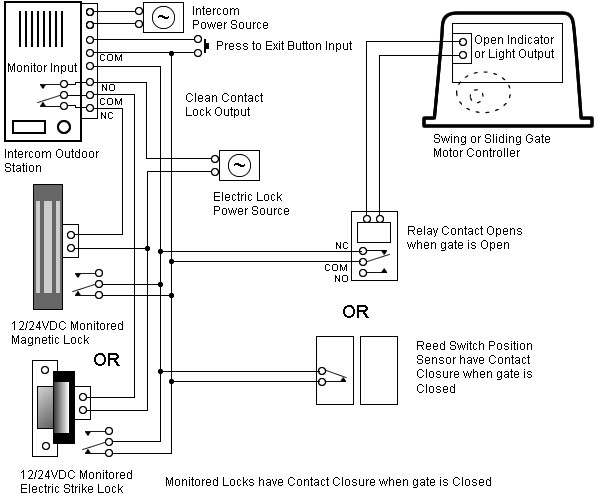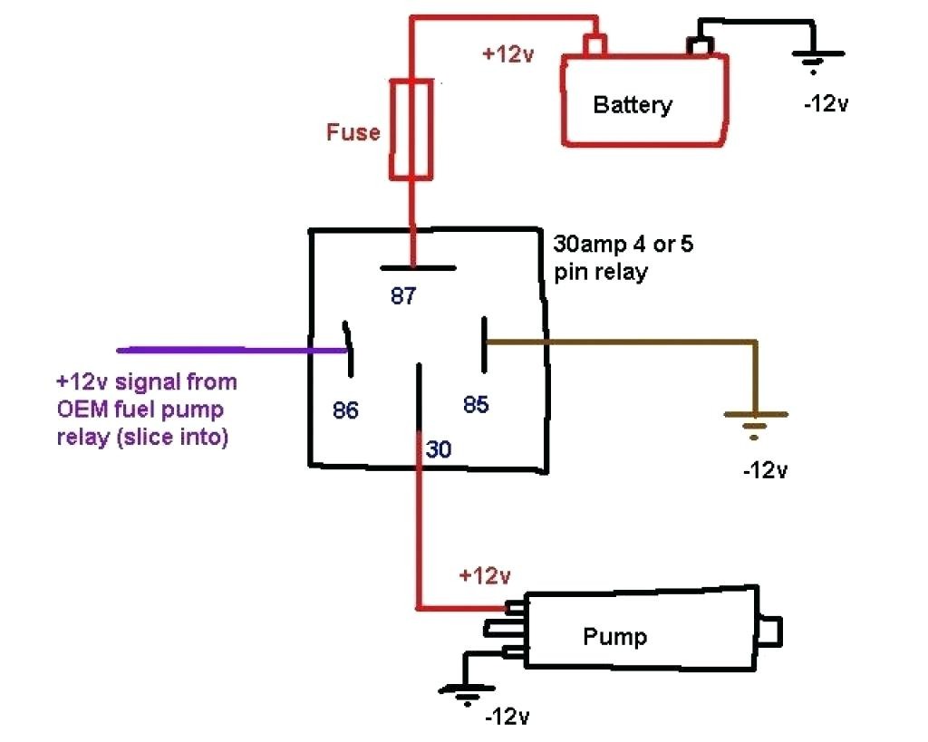
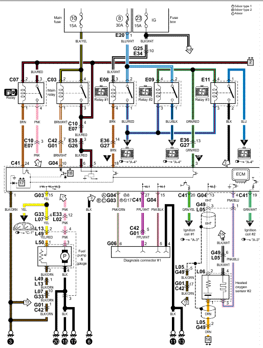
vehicle, review the simplified wiring diagram pictures below to make sure all of your connections are correct: To ground (-). Relay terminal 3.
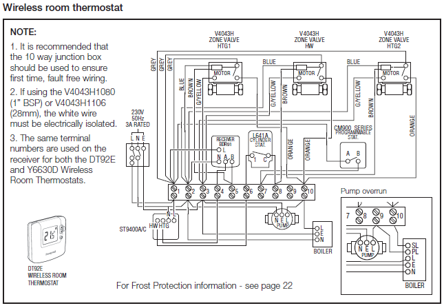
To vacuum switch. SSBC Re:Replacement Vacuum Pump Relays, wiring related issues. Start Capacitor wiring diagram needed I have an old AO Smith water pump.
vehicle, review the simplified wiring diagram pictures below to make sure all of your connections are correct: To ground (-). Relay terminal 3.
To vacuum switch. Begin electrical wiring by mounting the relay in a suitable location.
start the vehicle, review the simplified wiring diagram pictures below to make sure all of. Axle Flange Diagrams · Competition Series Calipers · Solutions Center · FAQ’s · Ask our Tech · GM Body Codes · Mopar Body Codes · Mustang Generation Info.vehicle, review the simplified wiring diagram pictures below to make sure all of your connections are correct: After confirming all connections are correct, you are ready to test run the system. Turn IGN to ON or ACC position; the pump should then kick on and will run up to inches before the regulator shuts the pump down.
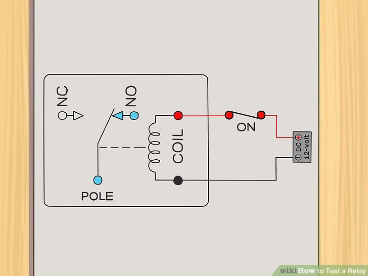
Relay Wiring Diagram.
A relay is typically used to control a component that draws high amperage. The relay allows full power to the component without needing a switch that can carry the amps. The switch only controls the relay.
The relay then provides a direct connection to the battery. The following diagrams show some common relay wiring schemes that use 4 pin ISO mini relays. 1.
Ad d i n g driving lights that come on with the headlight main beam: This simple circuit uses the power feed to the headlight main beam bulb as the trigger to energise a relay. The high current circuit in this relay feeds power to the driving light. The square relay pinout shows how the relay socket is configured for wiring. This pinout image is only a 2-pole diagram for room on the page purposes, but you can get the picture here with this one since a 3-pole will just have 1 more set of contacts.
Jul 24, · I’d wire it with a fuse as close to the power source as possible and connect it to the red wire on the motor. I’d use this switch on the ground side and connect it to the black wire on your motor. The switch would complete the circuit (make the motor run) somewhere in the in/hg range.New Electric Brake Vacuum Pump Relay for Booster schematron.org: Car & MotorbikeHow To Wire A Relay
