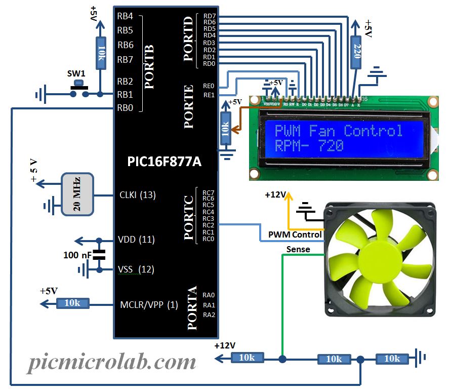
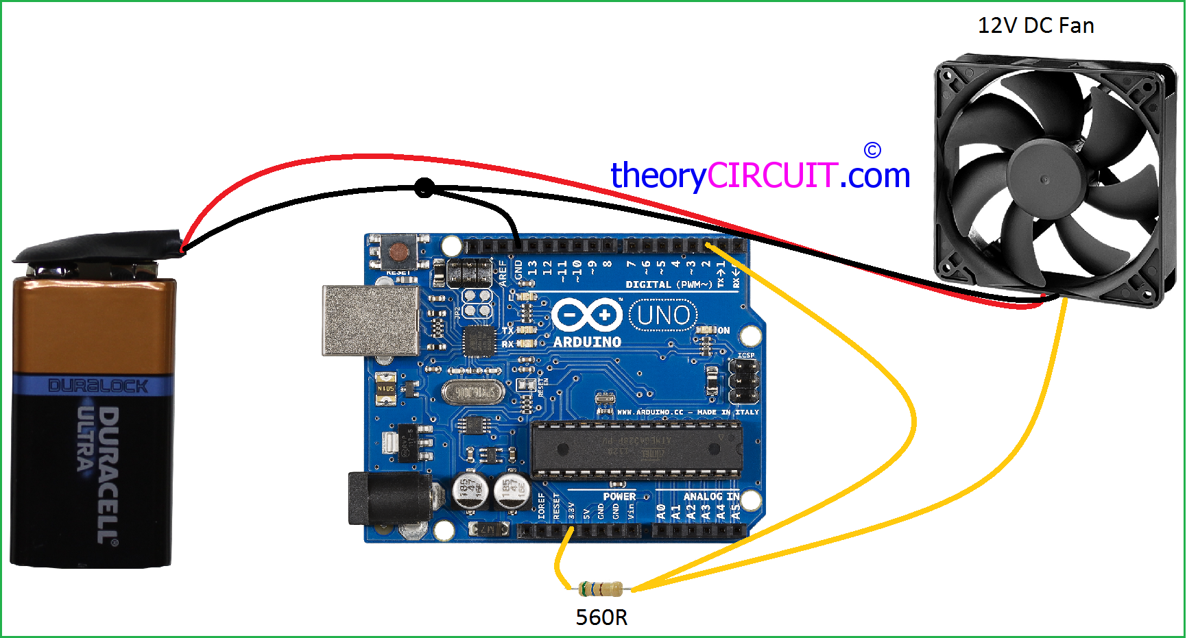
Keywords: fan control, temperature sensors, PWM Related The basic DC brushless fan is a 2-wire device over which a DC voltage is applied. That is all it .
As always, with all DC-DC converters, care must be taken during layout. Figure 7. I2C-compatible interface make it ideal for fan control in a wide range of .
V V. 3.
mA . Figure 1.
I2C Timing Diagram Open-Drain Output to 4-Wire Fan’s PWM Input or (Less Frequently) to Power Transistor Modulating. I2C-compatible interface make it ideal for fan control in a wide range of .
V V. 3. mA .
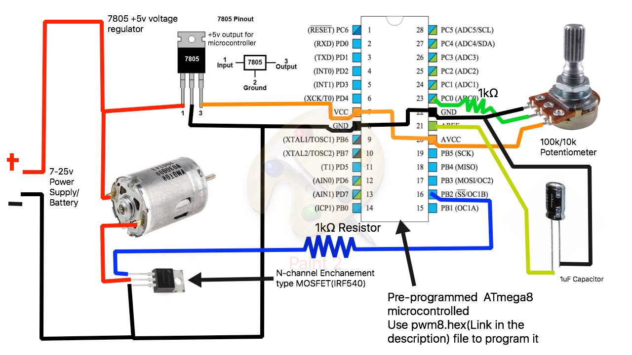
Figure 1. I2C Timing Diagram Open-Drain Output to 4-Wire Fan’s PWM Input or (Less Frequently) to Power Transistor Modulating.
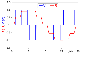
a P Cooling Fan Relay 1 Control Circuit), and shortly thereafter my Jeep overheated. as a lot of mis-information about the L “Pentastar” Jeep Wrangler my “best guess” based on the owner’s manual, I quickly realized this the only voltage going to the fan (other than the piddly PWM wire) is.
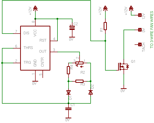
The TC is a switch mode, fan speed controller for Functional Block Diagram Electrical Characteristics: Unless otherwise specified, TMIN FAULT Output. Pulses appearing at SENSE due to the PWM turning.Feb 10, · That is what the Corvette Controller box does. If, in my above example, I set the duty cycle to 25% at a specific condition, and I send that information to the Corvette Controller via PWM, that controller will generate a voltage which is 25% of the full-range supply voltage, or or .
Fried fan wiring? Derale’s PWM Fan Controller is the missing link to any high-po Chrysler cooling system. A cooling system can sometimes be a buzzkill.
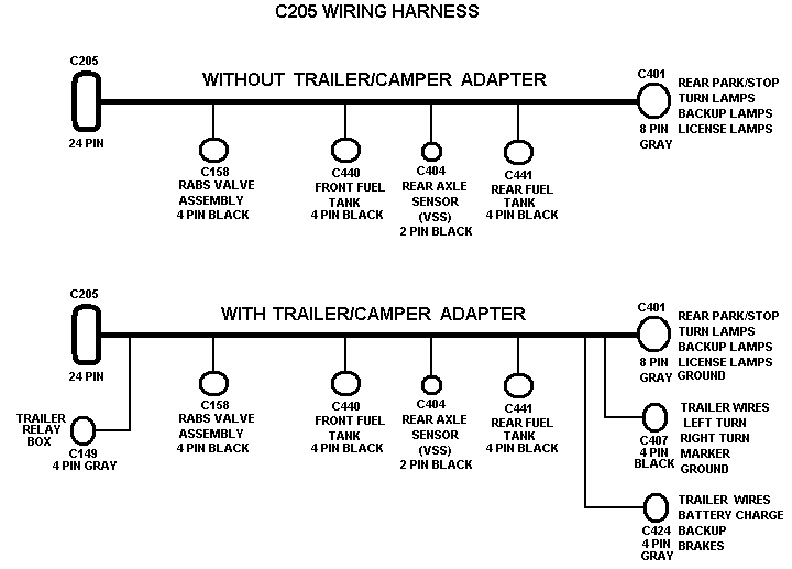
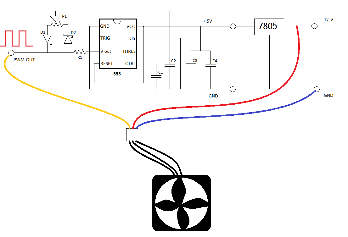
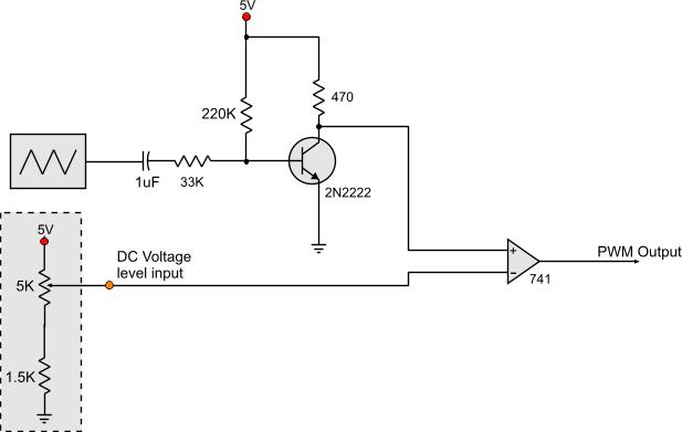
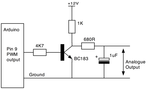
The PWM fans / connection is indeed more efficient as for power waste and management of your fan speeds allowing them to work also at less than 50 of their maximum speed and managing a more. PWM Dimmer/Motor Speed Controller ♥♥ This is diagram about PWM Dimmer/Motor Speed Controller you can learn online!!
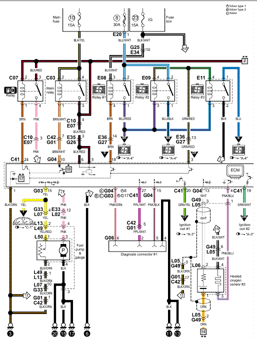
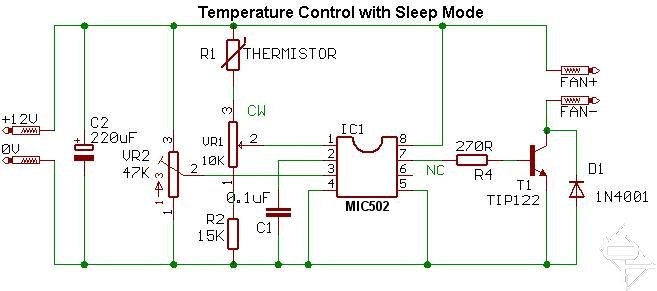
supply to limit the current if you have made a mistake in the wiring. The total current drain is about mA with the pot fully off, rising to Circuit Converts PWM Fan Drive to Linear and Reduces Acoustic Noise; KIA. HHO PWM Controller Circuit Diagram For – Pwm fan wiring diagram: 22 wiring diagram images wiring.
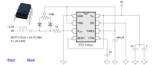
The very easiest way for beginners to continue learning how to read circuit diagrams is to adhere to the course and build the circuits from every schematron.orgent References.PWM Motor Speed Control Circuit with Diagram for DC MotorPWM fans on voltage controller? – [Solved] – Components
