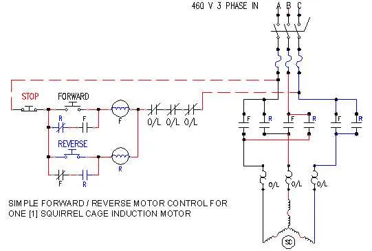
Ensure correct sequencing of the input leads to avoid damage and guarantee smooth operation when altering the rotation direction of a high-power electric motor operating at industrial voltage levels. Proper arrangement of the three conductors is critical for safe and efficient functioning.
Use appropriately rated contactors and overcurrent protection devices when configuring the control system to handle the substantial current load. Confirm all terminals are securely tightened and insulated to prevent accidental shorts or faults.
Follow standardized conventions for swapping two of the three conductors on the output side of the controller to change rotation direction. Precise labeling and verification of connections reduce troubleshooting time and enhance system reliability.
Identifying Terminals and Connection Points on a 3-Wire Motor Controller
Begin by locating the main input terminals labeled L1, L2, and L3, which serve as the power entry points. These are typically grouped together and clearly marked for incoming conductors.
Next, find the output terminals designated T1, T2, and T3; these connect directly to the motor leads. Their placement usually mirrors the input set but may be arranged to accommodate reversal of current flow.
Check for auxiliary contacts or control terminals often marked as A1, A2, or similar, which handle coil activation. These points are essential for energizing the mechanism that changes rotational direction.
Ensure all terminals are clearly numbered and distinguish between line and load connections to prevent incorrect attachment. Use a multimeter to verify continuity and confirm proper terminal functions before finalizing connections.
Note the presence of jumper bars or internal links that may require repositioning to enable alternate rotational states. Proper identification of these components is crucial for accurate operation.
Step-by-Step Connections for Reversing Motor Rotation Direction
To change the rotation of a motor, the key is to swap two of the three input conductors. This process involves using a control device to manage the current flow to the motor’s terminals. Follow these steps for successful installation:
1. Begin by ensuring the power supply is turned off before starting any work. Always verify with a multimeter that there is no current running through the system.
2. Identify the terminals on the motor and control panel. The three wires that supply power to the motor need to be clearly marked for connection purposes.
3. Connect the first conductor to terminal L1 of the control unit. This will be the main feed from the power source. Ensure the connection is secure to avoid loose contacts.
4. Attach the second conductor to terminal L2, which also serves as one of the incoming power lines. Securely fasten this wire to avoid disruption in current flow.
5. The third conductor should be connected to terminal L3, completing the path for the motor. This connection is crucial to establish a functional circuit for the operation.
6. Now, to reverse the motor’s rotation, swap the connections of two of the incoming power lines (for example, interchange the wires at L2 and L3). This will change the direction in which the motor turns when energized.
7. After making the changes, double-check each connection for tightness and proper insulation to prevent short circuits or accidental disconnections.
8. Once everything is in place, restore power to the system. Test the motor by briefly turning it on and observing its rotational direction. If it spins in the desired direction, the job is complete.
By following these clear steps, the motor’s rotation can be easily reversed for various operational needs.
Safety Checks and Troubleshooting Common Circuit Errors in Motor Controls

Before engaging in any maintenance, always disconnect the power supply to the system to prevent accidents. Verify that the control panel is de-energized using a reliable testing device.
Check the connections for signs of wear or overheating. Overheated terminals or melted insulation are indicators of poor contacts or excessive load. Ensure that each terminal is securely tightened and that wires are of the proper gauge for the expected current.
If the system fails to reverse direction or behaves erratically, inspect the contactors and relays for signs of damage or corrosion. Faulty contacts often result in inconsistent operation, or the inability to switch between forward and reverse actions.
Incorrect motor operation, such as failure to start, can be caused by incorrect connection of the control elements. Double-check that the auxiliary contacts align with the proper positions in the control scheme. Any misalignment will result in malfunction or complete failure to engage.
Ensure that the protective components, like circuit breakers or fuses, are rated correctly for the motor’s current draw. Overcurrent protection is vital to avoid permanent damage. If the fuse or breaker trips repeatedly, there may be a short circuit or overload in the system.
Lastly, inspect the mechanical parts of the system. Sticking or misaligned parts can prevent proper operation even if the electrical connections are intact. Clean and lubricate any moving components regularly to avoid wear and mechanical failure.