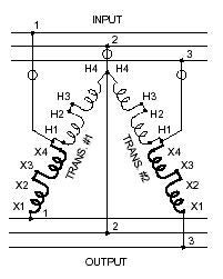
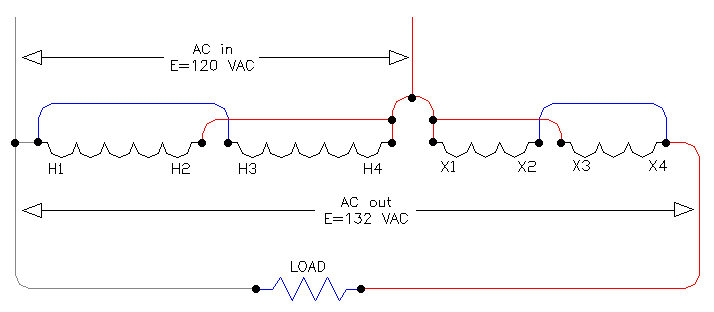
Buck – Boost Connection Diagrams. Buck-Boost transformers are single phase , four winding transformers Simply bring in three wires on the line side and. 16/32, or 24/48 (depending on the model) use the wiring diagram located on the inside of the cover to the wiring compartment.
If you are using this unit as an auto transformer to buck (lower) or boost (raise) the voltage by 3-Phase Wye Chart. C.
Connect using wiring diagram #4 in Buck & Boost literature 2. If load is three phase 3-wire: A.
Use same procedure as in single phase except two transformers . C.
Connect using wiring diagram #4 in Buck & Boost literature 2. If load is three phase 3-wire: A.
Use same procedure as in single phase except two transformers . Wiring Diagrams. Buck-boost transformers are an economical way to correct this potentially very .
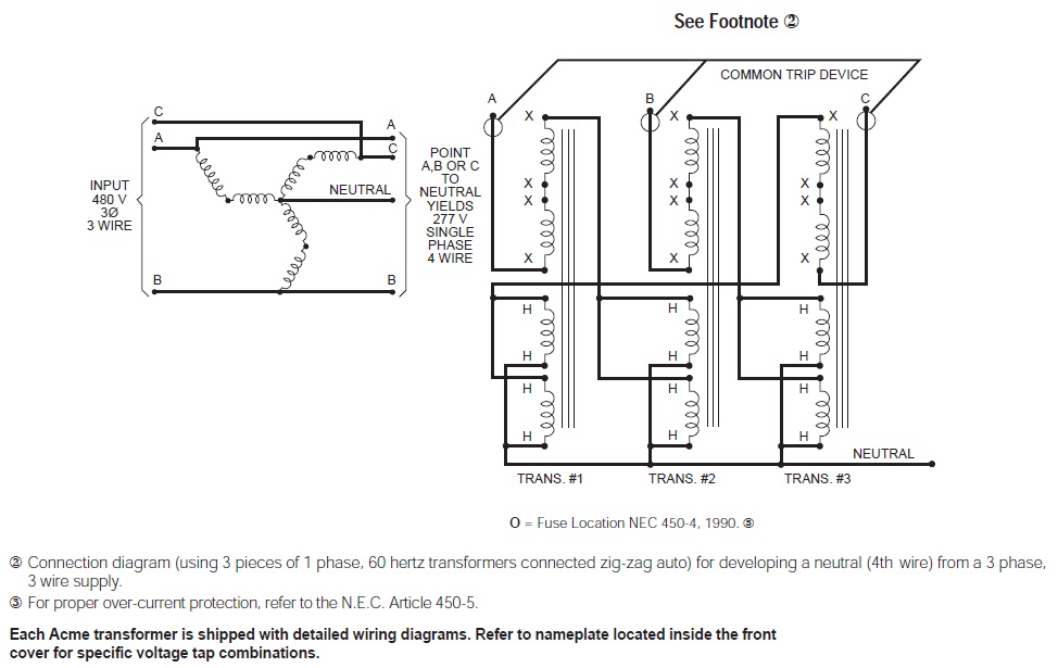
A three phase “wye” buck-boost transformer connection.Buck – Boost Transformer Terms & Definitions Buck-Boost transformers are single phase, four winding transformers designed for two purposes. The first purpose is as a low voltage isolation trans-former for use on 12, 16, 24, 32, or 48 volt circuits.
When used as low voltage transformers, Buck-Boost transformers have capacities of kVA to Three Phase Buck Boost Transformers are available despite that Buck Boost Transformers are often described as small single phase products. The difference is that two or three single phase transformers can be ganged together separately, or combined on the same core, to service three phase operations. C.
Connect using wiring diagram #4 in Buck & Boost literature 2. If load is three phase 3-wire: A. Use same procedure as in single phase except two transformers must be used.
Example: If load is 27 amperes, multiply 27 x 24V = VA, choose (2) catalog number SV43F B. Connect using wiring diagram #6 in Buck & Boost literature 3. incorrect supply line voltage can cause equipment failure.
Buck-boost transformers can correct line voltage within 5 to 25% of nominal. Steps for Selecting Buck-Boost transformers The following information is required before selecting a buck-boost transformer: 1.
Line Voltage – The voltage that you want to buck (decrease) or boost (increase). Buck Boost Electronic Calculator, Calculates proper Square D Transformers to use when doing small changes in voltage: 5%, %, 10%, %, 20%, and % Step One: Single Phase or Three Phase .Neutral required on the LINE side of 3 buck-Boost transformers from Buck and Boost Transformer Calculator – Schneider Electric United States
