Start by identifying the three input terminals, typically labeled U, V, and W. These correspond to the supply lines and are connected to the stator windings. For a star connection, join the ends of the coils together and feed power into the other ends. In a delta configuration, connect each end of one coil to the start of another, forming a closed loop.
Use a multimeter to verify continuity across each winding. The resistance between any two terminals should be approximately equal. If one pair shows a significantly different reading, check for damaged windings or poor connections. Always ensure insulation resistance exceeds 1 MΩ using a megohmmeter before energizing the system.
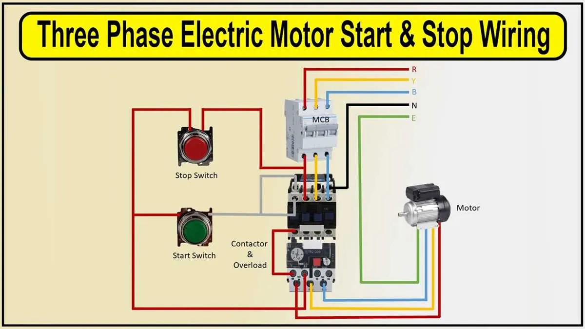
Control systems often include a contactor, overload relay, and thermal protection. The contactor enables remote switching, while the relay cuts power if the current exceeds safe limits. For precise operation, wire the control circuit through a normally closed stop switch and a normally open start button in series with the relay coil.
Direction of rotation can be altered by swapping any two supply lines. This reverses the rotating field, which changes the direction of shaft movement. Never attempt this while the unit is running. Always isolate power before making wiring changes.
3 Phase Electric Motor Diagram

Connect L1 to terminal U1, L2 to V1, and L3 to W1. Ensure the sequence matches the clockwise rotation requirement. Reverse two incoming lines to change direction.
Winding configuration: use either delta (Δ) or star (Y). For delta, link U2 to V1, V2 to W1, and W2 to U1. For star, connect U2, V2, and W2 together, and apply supply to U1, V1, W1.
Protection tip: integrate a thermal overload relay between contactor and windings. Set trip current to 1.15 times nominal rating.
Use a three-pole circuit breaker upstream. Confirm voltage compatibility: 400V for delta, 690V for star (assuming IEC standard).
Control circuit: wire the start button in series with a normally closed stop and the contactor coil. Include auxiliary contacts for self-latching.
Label all terminals clearly: U1, V1, W1 for input; U2, V2, W2 for return. Match wire gauge to rated current, typically 1.5 mm² per 10A.
Wiring Connections in a 3 Phase Motor: Star and Delta Configurations
Use star connection when starting torque requirements are low and current limitation is critical. Link terminals U1, V1, W1 to incoming lines, and bridge U2-V2-W2 together. This setup suits devices rated for 400V line-to-line with a 230V line-to-neutral design.
Switch to delta arrangement for full power operation. Join U1 to W2, V1 to U2, W1 to V2, then apply supply lines to U1, V1, W1. This layout maximizes torque and is ideal for continuous-duty tasks under full load. Avoid using delta on equipment designed exclusively for star input to prevent overheating and insulation failure.
Confirm nameplate voltage ratings before configuration. Mismatched setups cause excess current, reduced lifespan, and risk of thermal damage. For dual-voltage units, star fits high-voltage supply; delta matches lower-voltage input. Always verify with a multimeter after connection before energizing.
Understanding Motor Terminal Markings: U1, V1, W1, U2, V2, W2
Always identify U1, V1, W1 as input terminals and U2, V2, W2 as output connections. Incorrect pairing leads to reverse rotation or imbalance.
- U1 connects to U2, V1 to V2, and W1 to W2 for standard winding continuity checks.
- To reverse shaft rotation, swap any two supply lines connected to U1, V1, W1.
- In star configuration, join U2, V2, W2 together; apply voltage to U1, V1, W1.
- For delta setup, connect U1 to W2, V1 to U2, and W1 to V2.
- Use an ohmmeter to verify symmetry between U1–U2, V1–V2, and W1–W2; resistance should be equal.
- Markings may vary slightly depending on manufacturer; consult terminal box cover or data plate.
Never energize the system without confirming correct identification of all six terminals. Mistakes can result in mechanical damage or trip protection devices.
How to Read a 3 Phase Motor Schematic for Installation and Troubleshooting
Start by identifying the terminal block labeled U, V, and W. These correspond to incoming line conductors. Confirm continuity using a multimeter before connecting any supply.
Next, locate thermal overload contacts–often labeled “OL” or with normally closed symbols. These are wired in series with control voltage to prevent operation under excessive heat. Bypass testing must never be done live.
Check the control circuit for push buttons: “Start” is usually a normally open contact, and “Stop” is normally closed. Follow wire numbers from these buttons to the contactor coil, labeled “A1” and “A2.” Voltage across these terminals energizes the starter.
Examine auxiliary contacts labeled 13-14 or 53-54. These maintain holding current after the “Start” button is released. If missing or miswired, the unit will not stay energized.
Review connection points for grounding. Symbols with three horizontal lines or “PE” indicate protective earth. Ensure bonding continuity to the frame before energizing.
Finally, verify arrow symbols or delta/star notations to confirm internal configuration. An incorrect wiring pattern causes torque imbalance or tripping during load.