
A 3-way fuel valve diagram is a visual representation of the three different directions fuel can flow in a fuel system. This diagram is commonly used in automotive and other machinery to illustrate the various fuel line configurations and how they control the flow of fuel to different parts of the system.
Typically, a 3-way fuel valve has three ports labeled “inlet,” “outlet,” and “return.” The inlet port is where fuel enters the valve from the fuel tank or another source. The outlet port is where fuel is sent to the engine or other components that require fuel. The return port is where excess fuel is sent back to the fuel tank or another designated location.
The diagram visually illustrates the connections between these three ports, as well as any additional valves or components that may be present in the fuel system. It helps technicians and mechanics understand how fuel flows through the system, enabling them to troubleshoot and diagnose any issues that may arise.
In addition to fuel supply and return lines, a 3-way fuel valve diagram may also include other features, such as a fuel filter, fuel pump, and pressure regulator. These components work together to ensure the proper flow and pressure of fuel throughout the system, resulting in optimal engine performance.
What is a 3 Way Fuel Valve Diagram?
A 3 way fuel valve diagram is a visual representation of the fuel valve system used in certain types of machinery or vehicles. The diagram illustrates the different components and their connections, allowing for a better understanding of how the fuel valve works and how fuel flows within the system.
The diagram typically consists of labeled lines, valves, and other symbols that represent the various parts of the fuel valve system. It shows the pathways through which fuel enters, exits, and is directed within the system. The diagram may also include annotations or descriptions to help explain the function of each component.
Components in a 3 Way Fuel Valve Diagram
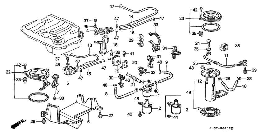
A typical 3 way fuel valve diagram may include the following components:
- Fuel tank: This is where the fuel is stored. The diagram may show the fuel tank as a labeled container.
- Fuel line: The fuel line connects the fuel tank to the fuel valve, allowing fuel to flow into the system.
- Fuel valve: The fuel valve controls the flow of fuel within the system. It may have multiple positions or settings, such as “on,” “off,” or “reserve,” and the diagram may show these positions.
- Branch lines: The diagram may include branch lines that connect the fuel valve to different components or subsystems within the machinery or vehicle.
- Engine: The diagram may show the engine or engines that receive fuel from the fuel valve.
- Other components: Depending on the specific system, the diagram may include additional components such as filters, pumps, or regulators to illustrate their connections and interactions with the fuel valve.
A 3 way fuel valve diagram is a valuable tool for understanding the fuel flow and system layout in machinery or vehicles that use this type of fuel valve system. It can be used for troubleshooting, maintenance, or simply for educational purposes to gain a better understanding of how fuel is managed within the system.
Understanding the Basics
In order to understand the functionality of a 3-way fuel valve, it is essential to grasp the basic principles of its operation. A 3-way fuel valve is a mechanical device that controls the flow of fuel to different components of a system. The valve consists of three ports, namely the main port, the intake port, and the outlet port. By manipulating the position of the valve, the flow of fuel can be directed accordingly.
The main port is the primary port through which the fuel enters the valve. From here, the fuel can be directed to either the intake port or the outlet port, depending on the position of the valve. The intake port is connected to a fuel source, such as a tank, while the outlet port is connected to the component or system that requires fuel.
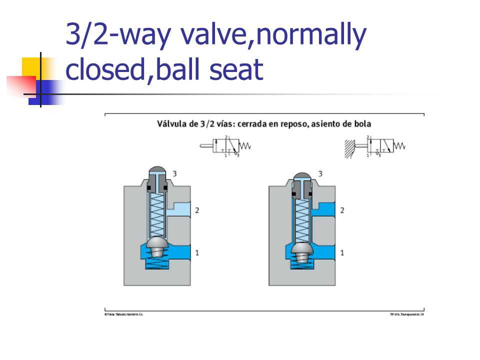
The 3-way fuel valve can be operated by various mechanisms, such as a lever, a knob, or a solenoid. When the valve is in the closed position, no fuel can pass through the valve, regardless of the position of the other ports. This is crucial for safety reasons and prevents any potential fuel leaks or accidents.
When the valve is in the open position, the fuel can flow freely from the main port to either the intake port or the outlet port. This allows for flexibility in directing the flow of fuel to different components or systems as needed. It is important to note that the valve must be positioned correctly to ensure the proper functioning of the fuel system.
In summary, a 3-way fuel valve is a mechanical device that controls the flow of fuel to different components or systems. By manipulating the position of the valve, the flow of fuel can be directed accordingly. Understanding the basics of how the valve operates is essential for its effective and safe use in various applications.
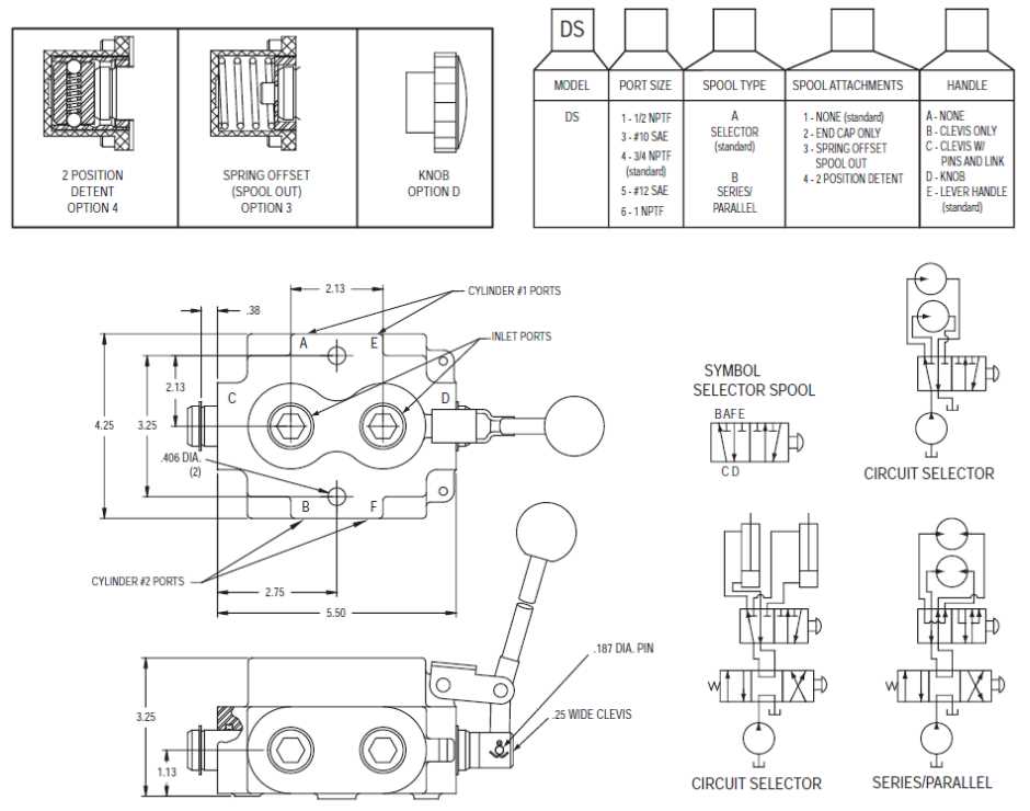
Key Components of a 3 Way Fuel Valve Diagram
A 3 way fuel valve diagram represents a critical component in fuel systems, allowing for the control and direction of fuel flow in different situations. It is typically used in applications such as small engines, motorcycles, and other vehicles. Understanding the key components of a 3 way fuel valve diagram is essential to comprehend its functionality and troubleshooting.
1. Inlet Port
The inlet port is the point where the fuel enters the valve from the fuel tank or another source. It is usually connected to a fuel line or hose. The inlet port is responsible for supplying fuel to the valve and is often equipped with a filter to prevent contaminants from entering the fuel system.
2. Outlet Ports
A 3 way fuel valve has two outlet ports, typically labeled as “OUT” and “RES” (reserve). These ports are used to direct fuel flow to different parts of the system. The “OUT” port supplies fuel to the engine or main fuel line, while the “RES” port provides fuel from the reserve tank in situations where the main fuel source is depleted.
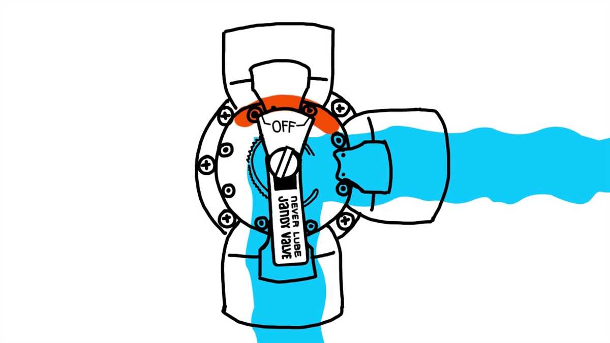
3. Switching Mechanism
The switching mechanism is the key component that allows the user to select the desired fuel flow direction. In a 3 way fuel valve diagram, this mechanism is often represented by a lever or knob that can be physically moved to control the position of internal valves. By switching between different positions, the user can determine whether fuel flows from the inlet to the “OUT” port, the “RES” port, or is shut off completely.
4. Internal Valves
The internal valves play a crucial role in a 3 way fuel valve diagram by controlling fuel flow based on the position of the switching mechanism. These valves are typically designed to open or close specific fuel passages, directing the fuel to the desired outlet port and preventing unwanted flow. They ensure that the fuel only follows the desired path as determined by the user’s selection.
5. Fuel Shut-Off
In addition to controlling fuel flow, a 3 way fuel valve diagram also includes a fuel shut-off feature. This feature allows the user to completely stop the flow of fuel when the engine is not in use, preventing potential leaks or fuel system faults. It is usually achieved by a specific valve position or a separate mechanism within the valve.
Understanding the key components of a 3 way fuel valve diagram is important for proper installation, maintenance, and troubleshooting of fuel systems. By familiarizing oneself with these components, one can effectively control fuel flow and ensure the smooth operation of engines and vehicles.
Common Applications for 3 Way Fuel Valves
Fuel valves are essential components in various systems that require the precise control of fuel flow. One type of fuel valve commonly used is the 3-way fuel valve. These valves are designed to regulate the direction of fuel flow between three different pathways. They are versatile and find application in a range of industries.
Aircraft Fuel Systems: One of the primary applications for 3-way fuel valves is in aircraft fuel systems. These valves are crucial in controlling the flow of fuel between the main fuel tanks, auxiliary tanks, and the engine. They ensure efficient fuel distribution and enable the aircraft to maintain balance during flight. The valves also aid in emergency situations, allowing the pilot to isolate fuel sources or transfer fuel in case of system failures.
Marine Fuel Systems: Another common application for 3-way fuel valves is in marine fuel systems. These valves play a vital role in diverting fuel between different tanks, such as the main fuel tank, auxiliary tank, and reserve tank. They enable efficient fuel management, allowing boats and ships to optimize fuel usage and ensure continuous operations. In emergency situations, the valves can be used to isolate fuel sources or reroute fuel to prevent accidents or system failures.
Industrial Machinery: 3-way fuel valves are also widely used in various industrial machinery that rely on precise fuel flow control. These valves can be found in generators, pumps, burners, and other equipment that require the efficient and accurate distribution of fuel. The valves allow for seamless transitions between different fuel sources, ensuring uninterrupted operation and preventing fuel starvation. They also provide the flexibility to isolate fuel pathways for maintenance or emergency situations.
Agricultural Equipment: In the agricultural sector, 3-way fuel valves are commonly used in tractors, harvesters, and other farm equipment. These valves enable the operator to switch between different fuel tanks, such as the main tank and auxiliary tanks, providing flexibility in fuel management. They also contribute to the longevity of the equipment by preventing fuel starvation and ensuring a consistent fuel supply during operations.
Overall, 3-way fuel valves are critical components in various systems that require precise fuel flow control. Whether in aircraft, marine vessels, industrial machinery, or agricultural equipment, these valves enable efficient fuel distribution, optimize fuel usage, and provide flexibility in emergency situations.
How to Read a 3 Way Fuel Valve Diagram
A 3 way fuel valve diagram is a visual representation of how a three-way fuel valve is structured and functions. It is an important tool for understanding the inner workings of this essential component of fuel systems.
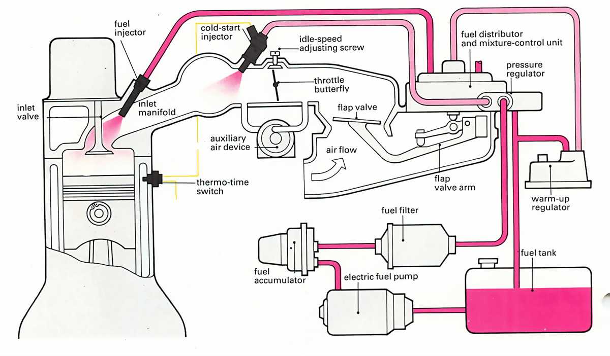
Key Components: The diagram typically shows the three key components of the fuel valve: the fuel inlet, the fuel outlet, and the fuel return. The fuel inlet is where fuel enters the valve from the fuel tank, while the fuel outlet is where fuel exits the valve and flows to the engine. The fuel return is a connection that allows excess fuel to be returned to the fuel tank.
Flow Paths: The diagram illustrates the different flow paths within the valve. It shows how fuel can be directed from the fuel inlet to either the fuel outlet or the fuel return. This allows for flexible fuel routing and control, depending on the requirements of the fuel system and engine.
Control Mechanism: The diagram also indicates the control mechanism of the valve, which is usually a lever or a switch. This control mechanism allows the operator to manually switch between the different flow paths to direct the fuel accordingly. For example, the operator may switch the valve to route fuel to the engine during normal operation, or to the fuel return during maintenance or in case of emergency.
Valve States: The diagram may show different valve states, where the fuel flow paths are labeled as open or closed. This helps to understand how the valve operates in different positions. For example, when the valve is in the closed position, fuel flow is blocked, preventing fuel from entering or leaving the valve.
Additional Information: Some diagrams may include additional information, such as pressure ratings, fuel line connections, and other relevant details. These details provide a more comprehensive understanding of the valve and its integration within the overall fuel system.
In conclusion, a 3-way fuel valve diagram is an invaluable resource for understanding the inner workings of a three-way fuel valve. By studying the diagram, one can gain insight into the components, flow paths, control mechanism, valve states, and other important aspects of this critical component in fuel systems.
Benefits of Using a 3 Way Fuel Valve Diagram
When it comes to maintaining and troubleshooting a fuel system, having a clear understanding of all the components involved is crucial. One such component is the fuel valve, which controls the flow of fuel within the system. To make it easier to understand how the fuel valve operates and fits into the overall fuel system, using a 3-way fuel valve diagram can provide several benefits.
1. Visual Representation
A 3-way fuel valve diagram offers a visual representation of the fuel valve and its connections to other components in the fuel system. This visual aid allows technicians and individuals to quickly identify the valve, understand its position, and trace its connections to other parts. By having a clear visual representation, it becomes easier to diagnose any issues or malfunctions within the fuel system.
2. Easy Identification of Components
With a 3-way fuel valve diagram, it becomes easier to identify the different components in the fuel system, such as fuel filters, fuel pumps, and fuel lines. The diagram provides a clear layout of the components and their positions relative to the fuel valve. This makes it simpler to locate specific components and understand their role in the overall functioning of the fuel system.
3. Efficient Troubleshooting
When a fuel system issue arises, having a 3-way fuel valve diagram can greatly streamline the troubleshooting process. By referring to the diagram, technicians can quickly identify the areas of the fuel system that may be causing the problem. This saves time and effort that would otherwise be spent on searching through the system blindly. The diagram acts as a guide to systematically follow and narrow down the potential causes of the fuel system issue.
In conclusion, using a 3-way fuel valve diagram offers numerous benefits when it comes to understanding, maintaining, and troubleshooting a fuel system. Its visual representation, easy identification of components, and efficient troubleshooting capability make it an essential tool for anyone working with fuel systems.
Troubleshooting and Maintenance Tips for 3 Way Fuel Valves
Proper maintenance and troubleshooting of 3 way fuel valves is essential to ensure their optimal functioning. Here are some tips to help you keep your fuel valve in good condition:
Cleaning and Inspection
Regularly clean the fuel valve to remove any debris and sediment that may be present. Use a soft brush or cloth to gently wipe away dirt from the valve. Inspect the valve for any signs of damage, such as corrosion or leaks. If any issues are detected, it is important to address them promptly to prevent further damage and ensure safe operation.
Checking for Proper Operation
Periodically check the operation of the fuel valve to ensure it is functioning correctly. Start by turning the valve to each position and verifying that it moves smoothly without any resistance. Check that the valve is securely tightened and there are no fuel leaks. If you notice any irregularities or difficulties in operating the valve, it may be necessary to repair or replace it.
Replacing Seals and O-Rings
The seals and O-rings in the fuel valve can wear out over time, leading to leaks or improper fuel flow. If you experience fuel leakage or notice a decrease in performance, it may be necessary to replace these components. Carefully remove the old seals and O-rings and replace them with new ones of the appropriate size and material.
Maintaining Fuel Quality
The quality of the fuel used can also affect the performance of the fuel valve. Ensure that you are using clean, filtered fuel to prevent clogs or contamination. Regularly replace the fuel filter to prevent debris from entering the valve. Additionally, consider using fuel additives or stabilizers as recommended by the manufacturer to maintain fuel quality and prevent buildup in the valve.
Consulting the Manufacturer
If you encounter any issues or have specific questions about troubleshooting or maintaining your 3 way fuel valve, it is always best to consult the manufacturer’s documentation or contact their customer support. They can provide you with accurate information and guidance based on the specific model and design of your valve.
By following these tips and performing regular maintenance, you can ensure the longevity and proper functioning of your 3 way fuel valve. Remember to always prioritize safety and consult professionals when in doubt.