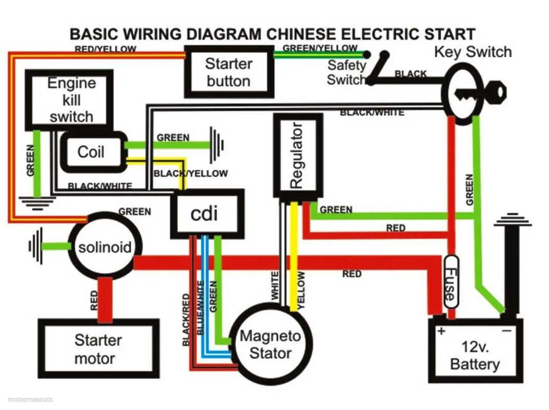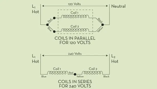
For optimal performance and longevity, it’s crucial to connect the three terminals of the electromagnetic actuator correctly. The first terminal is typically designated for the power supply, providing the necessary voltage to activate the mechanism. The second terminal is used for the control signal, often tied to a switch or relay that controls the actuator’s movement. The third terminal completes the system by grounding the circuit, ensuring a stable return path for the current.
Pin 1: Power Supply
This connection should be linked to a steady voltage source capable of meeting the actuator’s specifications. For most standard components, a 12V DC power supply is sufficient, though higher voltage systems may require a different setup. Double-check that the source provides consistent voltage to avoid fluctuations that could lead to malfunction.
Pin 2: Control Signal
This connection interfaces with a control switch, relay, or automation system. When the control system activates this pin, it triggers the electromagnet to engage or disengage. Ensure the control mechanism is properly rated for the component to avoid overloading the circuit.
Pin 3: Ground
The grounding pin is essential for ensuring the safe and effective flow of current. A proper connection to a ground point will help prevent electrical interference and minimize the risk of shorts. The ground must be securely connected to a known, reliable grounding point on the system or vehicle.
By following these guidelines, you ensure efficient operation and avoid common issues that arise from poor connections. Always verify the polarity of each connection before finalizing the setup.
3-Wire Component Circuit Setup

To properly connect a three-terminal actuator system, ensure that the positive terminal of the power supply is linked to the first input, often marked as “A” or “1”. The second connection, typically linked to the control switch, serves as the activation point for the unit. This connection is essential for triggering the function of the device.
The third terminal should be routed to the negative terminal of the power source, completing the loop and providing the necessary return path for current. Depending on the system’s design, the middle input may need a direct connection to the control switch for proper functionality.
Verify the correct polarity for each terminal to prevent malfunction. Ensure that the device’s activation point is securely connected to the switch, avoiding any loose connections that could interfere with operation.
In applications where precise activation control is required, using a relay to control the current flow through the middle terminal can enhance performance, ensuring the load is activated with minimal delay.
Wiring a 3-Wire Solenoid for Automotive Applications
To connect a 3-terminal actuator in automotive systems, follow these steps for a secure and effective setup:
First, identify the three terminals: the positive input terminal (often labeled “B”), the activation terminal (commonly labeled “S”), and the ground terminal (usually marked as “G”). Ensure the power supply is disconnected before beginning any installation.
Begin by linking the power source to the terminal marked “B.” This will provide the necessary current to the actuator. Use a reliable connector and ensure that the cable is properly insulated to prevent any accidental shorts.
Next, connect the activation terminal (“S”) to the control switch. This terminal should receive a pulse or continuous signal depending on the operation required. Use high-quality connectors that can withstand the operating voltage to maintain signal integrity.
Finally, the ground terminal (“G”) needs to be securely attached to the vehicle’s chassis or a dedicated ground point. A solid ground connection is critical to ensure proper function and prevent erratic behavior.
Once all connections are made, verify the setup by testing the function of the actuator. Check for any loose connections and ensure the control mechanism activates the system as expected. Always test the system under actual operating conditions to confirm reliability.
For added durability, consider using a weatherproof connector or a junction box if the actuator will be exposed to the elements. This will enhance the lifespan of the connections and protect against corrosion or physical damage.
Identifying Common Problems in 3-Wire Solenoid Circuits
Check for a complete connection between the three terminals. If the system fails to activate, inspect the continuity between each terminal. Broken connections are a common cause of malfunction.
Verify the voltage levels at the control and power terminals. Inadequate voltage may indicate a faulty power source or incorrect voltage input, preventing proper operation.
If the actuator doesn’t respond, ensure that the grounding connection is secure. A loose ground can lead to erratic performance or complete failure of the system.
Overheating is often a sign of excessive current draw. Measure the current across the circuit to ensure it matches the specifications of the components involved.
Test the control signal input to confirm it’s delivering the expected signal strength. A weak or fluctuating signal can cause improper activation, leading to erratic behavior or no response.
Inspect for any signs of corrosion or wear at connection points, which can increase resistance and hinder the flow of current, impacting the functionality of the system.
Step-by-Step Guide to Testing a 3-Wire Circuit
Follow these steps to test the functionality of your 3-wire circuit setup effectively:
- Ensure Power is Off: Before starting, disconnect all power sources to prevent accidental electrical shocks or component damage.
- Locate the Connections: Identify the terminals for input, ground, and activation. You should have a clearly marked control terminal for each function.
- Inspect for Damage: Visually check the components for any signs of wear, corrosion, or physical damage. This includes checking connectors and terminal screws.
- Test Continuity: Use a multimeter set to the continuity function. Place the probes across the terminals to check for a complete circuit path. The multimeter should emit a beep when continuity is present.
- Check Activation Voltage: Using a multimeter, measure the voltage between the control terminal and the ground. The voltage should match the required operating specifications for activation.
- Activate the Circuit: Apply the proper signal to the control terminal. Observe if the system responds as expected–either a physical movement or a voltage change on the output terminal.
- Measure Resistance: With the control terminal activated, measure the resistance between the power and activation terminals. The resistance should change significantly if the system is functioning correctly.
- Verify Grounding: Ensure the ground connection is solid. A poor ground can cause erratic behavior. Measure the voltage drop between ground and the negative terminal to ensure it’s within expected limits.
If any of the measurements fall outside the normal range, consider replacing the faulty components or checking for wiring issues.