
A 3-wire stator diagram is a visual representation of the electrical connections in a three-phase stator, which is a critical component of an electric generator or motor. Understanding the basics of a 3-wire stator diagram is essential for anyone working with electrical systems or machinery that use three-phase power.
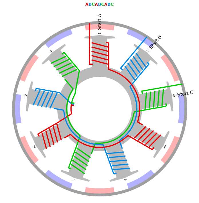
The diagram illustrates the arrangement of the stator windings in a three-phase system. It shows the three separate windings, labeled A, B, and C, which are spaced evenly around the stator core. Each of these windings is connected to one of the three phases of power supply.
In a 3-wire stator diagram, there are also connections shown for the neutral wire and the ground wire. The neutral wire provides a return path for the current, while the ground wire is used for safety purposes to prevent electrical shocks. These connections are essential for proper functioning and safety of the electrical system.
Understanding the Basics: 3-Wire Stator Diagram Explained
A 3-wire stator diagram refers to the diagrammatic representation of a 3-wire stator, which is a component commonly found in electrical and mechanical systems. In this diagram, the three wires are illustrated in relation to each other and their connections to other components or systems. Understanding the basics of the 3-wire stator diagram can help in troubleshooting and repairing electrical systems.
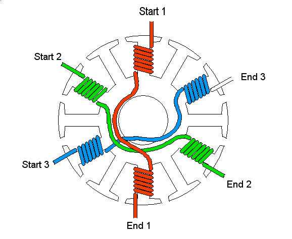
1. Three-Wire Configuration: The 3-wire stator diagram typically shows three separate wires, each with a unique purpose and connection. These wires may be labeled as A, B, and C or have different colors to indicate their function. It is essential to identify each wire correctly to ensure proper installation and functioning of the stator system.
2. Stator Connections: The 3-wire stator diagram also demonstrates the connections of the stator wires to other components or systems, such as voltage regulators or rectifiers. These connections can vary depending on the specific application and design of the electrical system. It is crucial to consult the diagram and follow the proper connection sequence to avoid damage or malfunction.
3. Purpose of Each Wire: The 3-wire stator diagram provides information about the purpose of each wire. Generally, one wire, often labeled as A, is responsible for generating the alternating current (AC) voltage. Another wire, typically labeled as B, serves as a neutral or common connection. The third wire, labeled as C, may be used for various purposes, such as voltage sensing or grounding.
4. Troubleshooting and Repair: The 3-wire stator diagram is an invaluable tool for troubleshooting and repairing electrical systems. By following the diagram and understanding the connections and purposes of each wire, technicians can identify faulty components or connections and rectify them accordingly. It is essential to have a good grasp of the diagram to ensure effective troubleshooting and repair.
Overall, understanding the basics of the 3-wire stator diagram is essential for anyone working with electrical and mechanical systems. By comprehending the three wires’ configuration, their connections, and their purposes, technicians can ensure proper installation and functioning, as well as efficiently troubleshoot and repair any issues that may arise.
What is a Stator and How Does It Work?
A stator is a crucial component in the operation of an electric motor or generator. It is an immovable part that surrounds the rotor and is responsible for generating a rotating magnetic field. The stator consists of a series of coils or windings, which are made of insulated copper or aluminum wire. These coils are arranged in such a way that when an electrical current flows through them, they produce a magnetic field.
The stator operates based on the principle of electromagnetic induction. When an electrical current is applied to the stator windings, it creates a magnetic field that interacts with the rotor. This interaction causes the rotor to rotate, resulting in the desired mechanical output. The stator plays a crucial role in converting electrical energy into mechanical energy, allowing electric motors and generators to function.
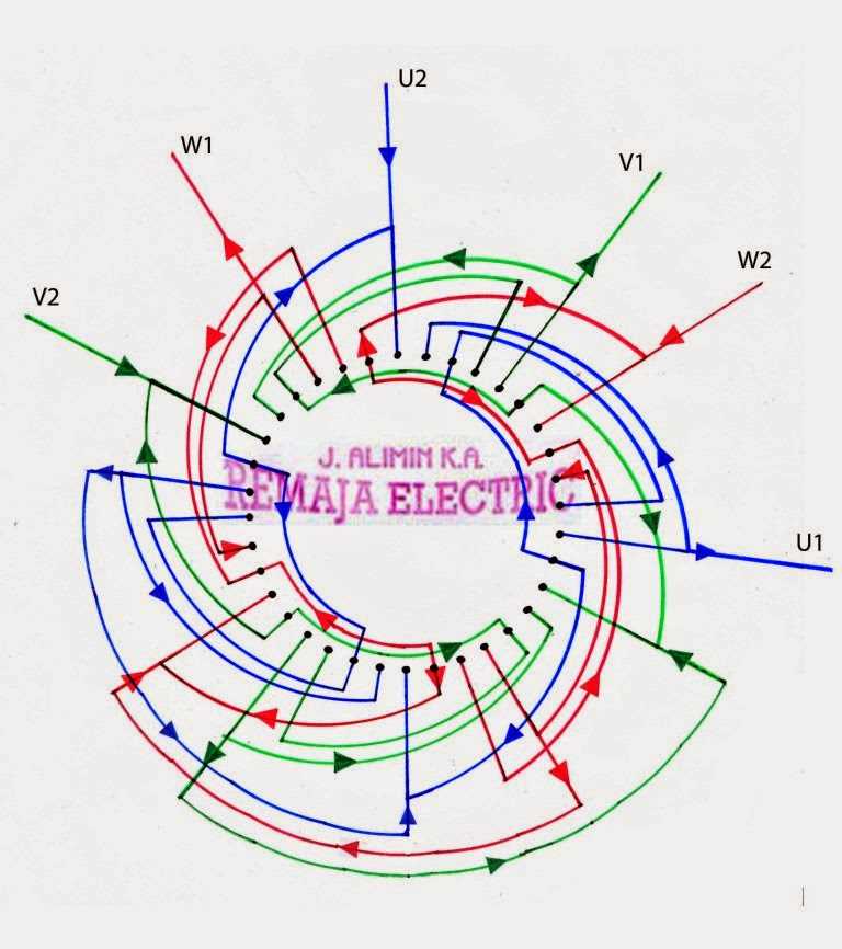
The stator’s design and configuration vary depending on the specific application and type of motor or generator. In a 3-wire stator diagram, for example, there are three separate windings, each connected to a different phase of the electrical supply. This configuration ensures a balanced and efficient operation of the motor or generator. The stator windings may be connected either in a star (wye) or delta (mesh) configuration, depending on the desired electrical output.
In summary, the stator is an integral part of electric motors and generators, responsible for generating a rotating magnetic field. It consists of coils or windings that, when energized with an electrical current, produce a magnetic field that interacts with the rotor. This interaction enables the conversion of electrical energy into mechanical energy, allowing for the operation of various industrial and household appliances that rely on electric motors and generators.
The Function and Importance of a 3-Wire Stator
The 3-wire stator is an essential component in a three-phase electrical system. It plays a crucial role in generating the necessary electrical power for various applications. A stator is a stationary part of an electric generator or motor that contains wire windings. These windings are responsible for converting mechanical energy into electrical energy, providing the power needed to operate different machines and devices.
The 3-wire stator consists of three sets of wire windings, typically arranged in a star or delta configuration. Each winding is connected to a specific phase of the electrical system. When an alternating current is applied to the stator, it induces a magnetic field that rotates within the stator. This rotating magnetic field is crucial for the operation of the generator or motor.
Function:
- Power Generation: The primary function of a 3-wire stator is to generate electrical power. As the magnetic field rotates within the stator, it induces an alternating current in the wire windings. This alternating current is then used to power various electrical devices, such as lights, motors, and appliances.
- Magnetic Field Generation: The rotating magnetic field generated by the 3-wire stator is essential for the operation of a three-phase electrical system. This magnetic field interacts with the rotor (for generators) or the stator (for motors) to create the necessary electromagnetic forces that facilitate energy conversion.
- Phase Balancing: In a three-phase system, phase balancing is essential to ensure the proper distribution of electrical power. The 3-wire stator helps maintain the balance between the three phases, ensuring a stable and reliable power supply.
Importance:
- Efficiency: The use of a 3-wire stator in a three-phase system allows for more efficient power generation and distribution. The three phases work together to evenly distribute the load, reducing energy losses and improving overall system efficiency.
- Power Capacity: The 3-wire stator enables the generation of a higher power capacity compared to single-phase systems. This increased power capacity is particularly beneficial for powering large industrial machinery and electrical systems.
- Reliability: The balanced design of the 3-wire stator helps ensure the reliable operation of the electrical system. By evenly distributing the load across the three phases, the stator reduces the risk of overloading and increases the system’s overall reliability.
In conclusion, the 3-wire stator plays a vital role in generating electrical power in a three-phase system. Its function of power generation and magnetic field generation, coupled with its importance in phase balancing, efficiency, power capacity, and reliability, highlight its significance in various industries and applications.
Components and Connections of a 3-Wire Stator
A 3-wire stator is an essential component in many electrical systems, including generators and alternators. It consists of various components and connections that work together to generate electricity. Understanding the different components and their connections is crucial for troubleshooting and maintaining these systems.
Components:
- Stator Core: The stator core is the central part of the stator, and it is typically made of stacks of laminated steel sheets. The core provides support and houses the other components.
- Coils: The stator coils are the winding of insulated copper wires around the core. These coils carry the electrical current and generate the magnetic field.
- Terminals: The terminals are the connection points on the stator where the wires are attached. They allow for the transfer of electrical current between the stator and other components.
- Insulation: Insulation is used to prevent electrical short circuits and ensure the proper flow of current within the stator. It is typically made of materials such as varnish or enamel.
Connections:
A 3-wire stator has three main connections:
- Phase Connections: The three stator coils are connected in a specific sequence known as the phase connections. These connections determine the direction of the electrical current flow and are crucial for the proper functioning of the stator.
- Ground Connection: The ground connection provides a path for electrical current to flow to the earth. It helps to protect the system from electrical faults and ensures safety.
- External Connections: The external connections are the points where the stator is connected to other components, such as the rotor or the electrical load. These connections allow for the transfer of electrical energy within the system.
Overall, understanding the components and connections of a 3-wire stator is essential for the proper functioning and maintenance of electrical systems. It ensures the efficient generation and transfer of electrical energy and helps in diagnosing and fixing any issues that may arise.
Wiring Diagram for a 3-Wire Stator
In electrical engineering, a stator is a stationary part of an electric generator or motor that surrounds the rotor. The stator consists of a core and multiple wire windings. One common type of stator is the 3-wire stator, which is used in many small engines and generators.
The wiring diagram for a 3-wire stator typically includes three wires: one for power, one for ground, and one for the output voltage. The power wire carries the electrical current from the power source to the stator. The ground wire provides a safe path for electric current to flow back to the power source. The output voltage wire carries the generated electrical energy from the stator to the load.
Typically, the 3-wire stator is connected to a rectifier, which converts the alternating current (AC) output from the stator to direct current (DC) that can be used by the load. The rectifier is often connected to a voltage regulator or controller, which maintains a constant voltage output to the load.
To ensure proper wiring and operation of a 3-wire stator, it is important to refer to the manufacturer’s wiring diagram or instructions. The wiring diagram will provide specific details on how to connect each wire and any additional components that may be required for proper operation.
In conclusion, the wiring diagram for a 3-wire stator is essential for ensuring proper electrical connections and operation. It is important to follow the manufacturer’s instructions and diagrams to ensure correct wiring and prevent any potential electrical issues or damage to the stator.
Common Issues and Troubleshooting
If you are experiencing issues with your 3-wire stator diagram, it is important to troubleshoot and identify the source of the problem. Here are some common issues and troubleshooting steps you can take:
1. No Output Voltage
If your stator is not generating any output voltage, there could be several potential causes:
- Faulty Stator: Check the continuity of the stator windings using a multimeter. If there is no continuity, the stator may need to be replaced.
- Short Circuit: Inspect the stator wiring for any signs of short circuits or loose connections. Repair or replace any damaged or faulty wiring.
- Diode Failure: Test the diode bridge rectifier to ensure it is functioning properly. Replace any defective diodes.
- Regulator/Rectifier Malfunction: Check the voltage regulator/rectifier unit for any signs of damage or overheating. If necessary, replace the unit.
2. Low Output Voltage
If your stator is generating a low output voltage, there could be several potential causes:
- Worn Brushes: Inspect the brushes and commutator for wear or damage. Replace any worn brushes.
- Bad Connections: Check all stator connections for tightness and cleanliness. Clean or tighten any loose connections.
- Coil Resistance: Measure the resistance of the stator coils using a multimeter. If the resistance is outside of the specified range, the stator may need to be replaced.
- Inadequate RPM: Ensure that the engine is running at the recommended RPM range. If the RPM is too low, the stator may not be able to generate sufficient voltage.
3. Overheating
If your stator is overheating, it could be due to the following reasons:
- Overloading: Check if the electrical load on the stator is within its rated capacity. Reduce the load if necessary.
- Insufficient Cooling: Clean any dirt or debris from the stator cooling fins and ensure proper airflow. Consider installing additional cooling measures, such as a fan or heat sink.
- Faulty Wiring: Inspect the stator wiring for any signs of overheating or damage. Repair or replace any faulty wiring.
- Regulator/Rectifier Failure: Test the voltage regulator/rectifier unit for proper functioning. Replace any defective components.
Remember, always refer to the specific wiring diagram and troubleshooting guide provided by the manufacturer for your particular 3-wire stator setup. If you are unsure about any aspect of troubleshooting or repairing your stator, it is recommended to seek professional assistance.
Benefits and Applications of Using a 3-Wire Stator
A 3-wire stator configuration offers several benefits and finds applications in various industries. It is widely used in electrical systems to generate and control electric power. Here are some of the advantages and applications of using a 3-wire stator:
Benefits
- Reliability: The 3-wire stator provides a robust and reliable power generation method. It ensures stable power output and can withstand varying load conditions.
- Efficiency: The configuration of a 3-wire stator allows for efficient power transmission and utilization. It minimizes power loss and maximizes system efficiency.
- Versatility: A 3-wire stator can be designed to work with different power sources and loads. It is adaptable to various applications and can be customized according to specific requirements.
- Simplicity: The 3-wire stator configuration is relatively simple compared to other power generation systems. It has a minimal number of wires and components, which simplifies the installation and maintenance processes.
Applications
The 3-wire stator is widely used in the following applications:
- Electric Generators: The 3-wire stator is a common configuration in electric generators used for residential, commercial, and industrial power supply.
- Wind Turbines: Many wind turbines utilize a 3-wire stator to convert the rotational energy of the blades into electrical power.
- Hydroelectric Power Plants: The 3-wire stator configuration is often employed in hydroelectric power plants to generate electricity from flowing water.
- Industrial Motors: Industrial motors, such as induction motors and synchronous motors, often incorporate a 3-wire stator for efficient and reliable operation.
- Automotive Alternators: Many vehicles use 3-wire stators in their alternators to generate electrical power for charging the battery and operating various electrical components.
Overall, the use of a 3-wire stator offers multiple benefits, including reliability, efficiency, versatility, and simplicity. Its applications span across various industries, making it a vital component in numerous electrical systems and power generation methods.