Easy wiring with plug-in omniconnect terminals for inputs, outputs and supply Technical data.
Input circuits. G – J – H. Input signals (see also configuration diagram) 10 50mA/0 1mA 1 5V/0 10V/2 10V/±10V 1MΩ.
± 55 mA 4. 5 . 6.
0 5 V. 0 10 V.
1 5 V. 2 10 V. 10 V.
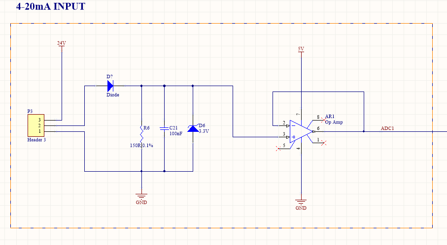
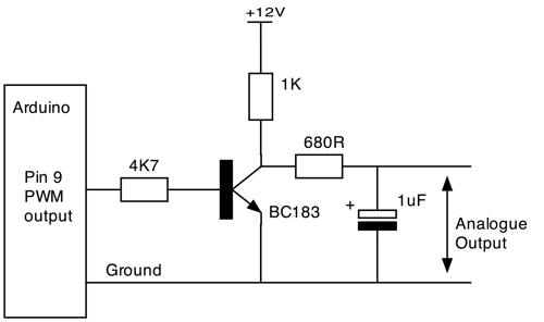
4-20mA Industrial Sensor + Arduino
0 1 mA. 0 20 mA. 4 20 mA.
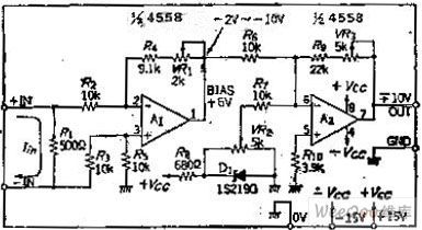
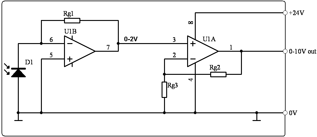
+20 mA, V, V, V, +/V, +/-5V or +/V analog signal input is circuitry is conformal coated and packaged in a Lexan DIN rail enclosure Universal Signal Converter with a mA input and +/- 10V output: USC- CVBB10V. V / V to mA signal converter.
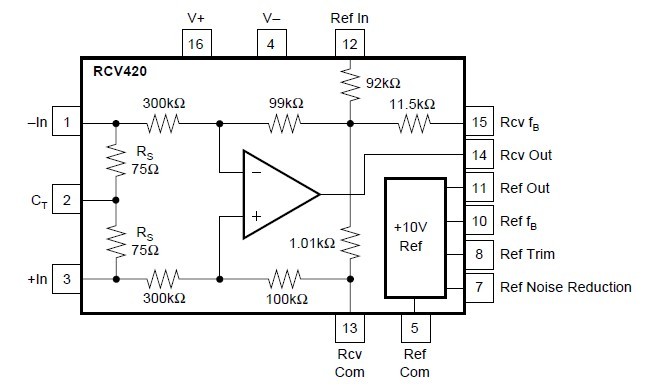
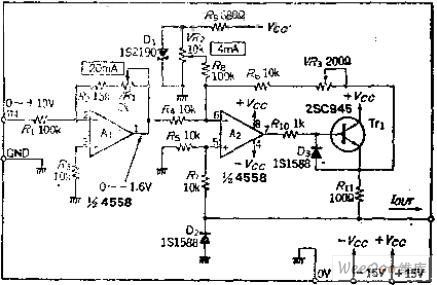
Thread starter mA signal. Can anyone help with this and provide a circuit diagram if posible.
Find mA To v Converter related suppliers, manufacturers, products and 4-Wire Isolated Transmitter, Universal Input, mA or V .. The LDO regulator is ideal for powering always-on circuitry in automotive applications.
4-20mA Industrial Sensor + Arduino
Typically these add a Ω shunt resistor across the 0 – 10 V input to convert schematic. Figure 1.

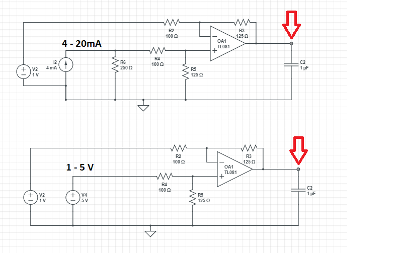
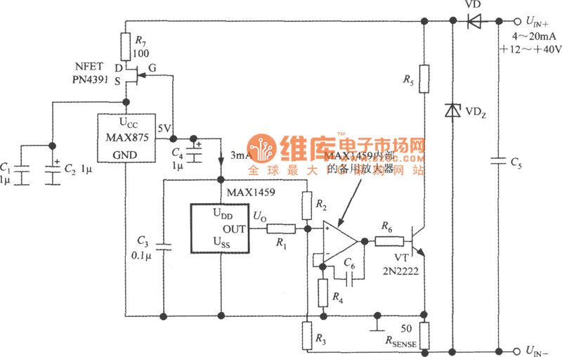
A 0 – 10 V / 4 – 20 mA input for V ADC.Abstract: This design idea describes a simple circuit that converts a mA signal to a 0V to 5V analog voltage ideal for conversion to digital with an analog-to-digital converter (ADC). The 4mA level from the transducer produces a 0V output and the 20mA level produces a 5V output.
Products ISOCON V to mA Signal Converter. The ISOCON isolating signal converter is used to convert a V input measurement signal to a mA current loop output signal.
The ISOCON can be easily mounted to a wall using a TS35 DIN rail. ISOCON-6 .
Calculating this drop must also consider the maximum level of current that can flow in the mA current loop—not 20mA, but the over-scale or alarm limit of the transmitter. Type II 2-Wire Circuit Transmitter Floats Relative to Ground Ω (V), 50Ω (V), and Ω (V).
Note also that you are not limited to a single. schematron.org offers 1, 4 20ma circuit products. About 6% of these are integrated circuits, 1% are circuit breakers, and 1% are other pcb & pcba.
A wide variety of 4 20ma circuit options are available to you, such as mini, residual current. You can also choose from free samples, paid samples.
Nov 24, · I have no problem getting mA. but it seems pretty hard to get an offset of 4mA, using like a op-amp.
I tried inputting a V and adding a 4V into a summing amplifier. to get V and running it thru 1K to get mA, but my summing amplifier doesnt work.How to get a 10 volt signal from a mA output pressure sensorConvert signal V to mA | All About Circuits