For any project involving a four-wire system, it’s essential to understand how each connection functions within the circuit. Whether you’re working on automotive repairs, home electronics, or other devices, knowing how to properly connect each terminal is crucial for proper operation. Follow this guide to ensure you’re connecting the right components in the correct order.
Step 1: Identify the purpose of each conductor. In a four-wire configuration, one wire typically serves as the ground, while the others manage power flow and data signals. Ensure you clearly differentiate between the power and control lines to avoid short circuits.
Step 2: Determine the required voltage for each terminal. Mismatched voltage can cause components to malfunction or fail. Always check the specifications before making connections to ensure you meet the operational requirements.
Step 3: Secure the wires tightly to prevent loose connections. A loose contact can lead to intermittent functionality or damage to components over time. Use the correct crimping or soldering tools for a solid and reliable connection.
Step 4: Perform a continuity test. Before powering up the system, ensure each line is properly connected by using a multimeter to check for continuity. This quick check can save you from potential issues during operation.
By following these straightforward steps, you’ll ensure the four-wire setup works smoothly, with minimal risk of failure or electrical hazards.
4 Pin Connection Setup: Practical Guide

When working with a four-terminal connection, it is essential to understand the specific roles of each terminal to ensure proper setup. Here’s a clear breakdown of how to handle such a system:
- Terminal 1: Typically used for input signals. Connect this terminal to the source device to provide necessary voltage or data.
- Terminal 2: This is commonly the ground or common connection. Ensure it is securely connected to the device’s ground or negative terminal to prevent electrical issues.
- Terminal 3: Often designated for power output. This terminal will supply the energy needed by the connected device or circuit.
- Terminal 4: Frequently serves as an output signal. Use this to transfer data or feedback from the device to another component.
For a reliable connection, always check the manufacturer’s specifications regarding voltage limits and polarity. Using incorrect values can cause malfunction or damage to your equipment.
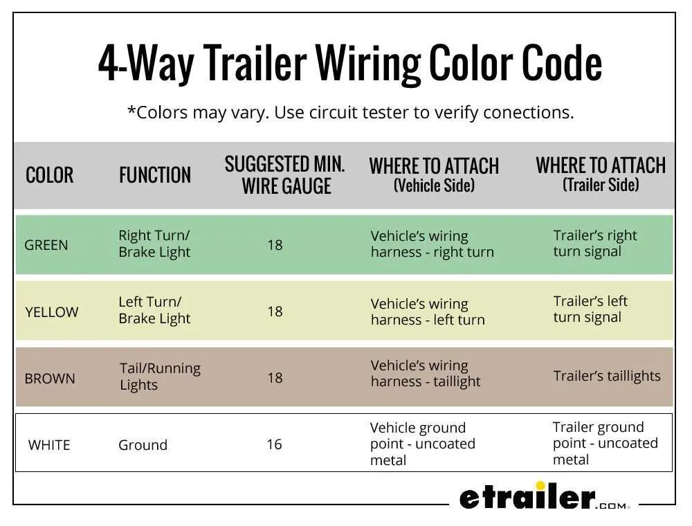
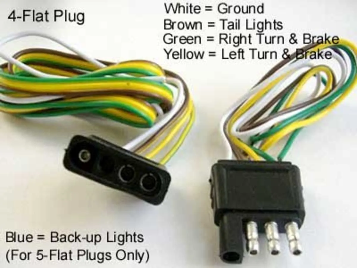
In some cases, it is advisable to use color-coding for easy identification and troubleshooting. For example, red for power, black for ground, and the other two for data or signals, depending on the specific use case.
Always double-check connections before powering up the system to avoid any short circuits or incorrect voltage application. If in doubt, consult the datasheet of the component for exact wiring instructions.
Understanding the Pinout of a 4 Pin Connector

When working with a 4-terminal interface, it’s crucial to identify the correct allocation of each terminal to ensure proper function. Always start by checking the manufacturer’s documentation for the correct color coding and terminal assignments. In most cases, these connectors are used for low-power signals or as power inputs, depending on the application.
Power and Ground are typically located at specific terminals. The first two positions are often dedicated to the supply voltage and the common ground. These connections should be double-checked for correct polarity before making any modifications to avoid damaging sensitive components.
Next, the remaining terminals usually serve for communication or data transfer. For instance, one could carry a clock signal while the other transmits or receives data. These outputs might vary in voltage depending on whether the connection is designed for analog or digital signals. Ensure that the corresponding wires are connected to the correct components to avoid interference or malfunction.
Tips: Always use a multimeter to verify the continuity of each connection and ensure there are no short circuits. Proper insulation and protection from external environmental factors can also enhance the longevity of the connector’s reliability.
Finally, when connecting a device that uses a 4-terminal arrangement, be aware of the maximum current ratings. Exceeding these limits could cause overheating and potential failure of the connection. Always use connectors rated for the appropriate current specifications.
How to Wire a 4 Pin Connector for Specific Applications
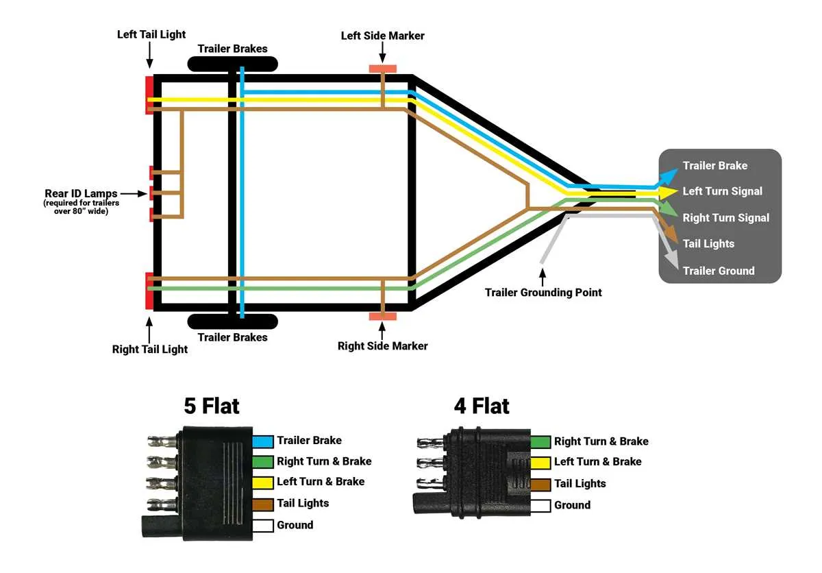
To properly connect a 4-terminal plug for specific tasks, start by identifying the role each terminal plays in the circuit. For example, in automotive lighting, one connection might be for ground, another for the positive supply, and the other two for control functions like signaling or braking.
For reliable performance, strip insulation off each conductor carefully, ensuring no fraying of the exposed wire. Insert the leads into the appropriate terminals, making sure each is securely fastened to avoid loose connections, which can cause intermittent faults or power loss.
When using this connector for low-voltage systems, like in LED installations, consider using tinned copper for better conductivity. If the task involves higher currents, opt for thicker gauge conductors to minimize heat buildup.
For waterproofing, use a sealed version of the plug or add a layer of heat shrink tubing around the connector after assembly to prevent corrosion, especially in outdoor applications. Ensure that the terminals are well-insulated and the connections are tightly secured to avoid any shorts or power leakage.
Double-check the pinout for your specific device, as some connectors may require customized setups depending on the application, such as reversing polarity for different functionalities.
Common Mistakes to Avoid When Wiring 4 Pin Connectors

Incorrectly matching the correct wire positions is one of the most frequent errors. Always ensure each wire corresponds to the designated terminal as per the manufacturer’s specifications. Misplacement can lead to malfunction or potential short circuits.
Another common mistake is overlooking the quality of the connections. Inadequate stripping of insulation or poor crimping can result in weak electrical contact, leading to intermittent performance or complete failure. Ensure the wire is stripped appropriately and the connector is firmly attached to avoid this issue.
Using wires that are not rated for the required current is also problematic. Always check the wire gauge against the system’s power requirements. Using undersized conductors can lead to overheating, causing damage to both the connector and the system it powers.
Failing to check for proper insulation and strain relief is another key mistake. When the cable is exposed to mechanical stress, improper protection at the entry point can cause the wires to break or fray, disrupting the electrical flow. Use appropriate grommets or strain-relief mechanisms to maintain long-term durability.
Never skip testing your connections before final installation. It’s easy to assume the setup is correct, but a simple continuity test can reveal issues that are otherwise hard to detect. Verifying with a multimeter ensures that all connections are functional and properly established.
Lastly, ignoring the orientation of the components can result in incorrect assembly. Certain connectors and components have a specific alignment that must be followed for the system to work correctly. Double-check the orientation of the connector before securing everything into place.