
A multiplexer, also known as a mux, is a combination circuit that combines multiple input signals into a single output signal. It is widely used in digital electronics, particularly in data transmission and communication systems. One commonly used multiplexer is the 4 to 1 multiplexer, which has four input lines and one output line.
The 4 to 1 multiplexer circuit diagram consists of four input lines labeled A, B, C, and D, and one output line labeled Y. It also has two select lines labeled S0 and S1. The select lines determine which input line is connected to the output line.
The truth table for a 4 to 1 multiplexer shows the relationship between the input lines, select lines, and output line. When S0 and S1 are both low (0), the input line A is connected to the output line Y. When S0 is low (0) and S1 is high (1), the input line B is connected to the output line Y. Similarly, when S0 is high (1) and S1 is low (0), the input line C is connected to the output line Y. Finally, when both S0 and S1 are high (1), the input line D is connected to the output line Y.
The 4 to 1 multiplexer circuit diagram is a useful tool for understanding how a multiplexer works and how it can be used in various applications. It allows engineers and technicians to design and implement multiplexing systems that efficiently combine multiple signals into a single output. By using multiplexers, data transmission and communication systems can be more compact, cost-effective, and efficient.
Understanding the 4 to 1 Multiplexer Circuit Diagram
The 4 to 1 multiplexer is a digital circuit that allows for the selection of one out of four input signals to be routed to the output. It is commonly used in various applications, such as data routing, data selection, and multiplexing. Understanding the circuit diagram of a 4 to 1 multiplexer is essential for working with digital logic circuits.
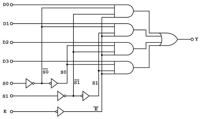
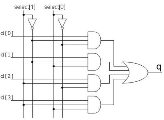
The circuit diagram of a 4 to 1 multiplexer typically consists of four input lines (A, B, C, and D), two control lines (S0 and S1), and one output line (Y). The control lines determine which input signal is selected and routed to the output. The S0 and S1 lines can have different combinations of logic levels (high or low) to select the desired input. Each input line is connected to a corresponding AND gate, and the outputs of the AND gates are connected to a common OR gate. The output of the OR gate represents the selected input signal.
By analyzing the circuit diagram, it is possible to understand how the control lines and input lines are interconnected and how they affect the selection of the output signal. The control lines act as selectors, and based on their logic levels, the corresponding input signal is connected to the output. For example, if S0 is low and S1 is high, the input signal connected to line C will be selected and routed to the output. If both control lines are low, no input signal will be selected.
When working with the 4 to 1 multiplexer circuit, it is important to understand the truth table that defines the behavior of the circuit based on the input states. The truth table lists all possible combinations of the control and input lines and indicates which input signal will be selected for each combination. This information is crucial for designing and troubleshooting digital circuits that utilize 4 to 1 multiplexers.
Components of a 4-to-1 Multiplexer
A 4-to-1 multiplexer is a digital logic circuit that allows multiple inputs to be selected and connected to a single output based on control signals. It is commonly used in many electronic systems where the selection of different input signals is required.
The main components of a 4-to-1 multiplexer include:
- Data Inputs: A 4-to-1 multiplexer has four data inputs labeled D0, D1, D2, and D3. These inputs are the sources of the data that can be selected and connected to the output.
- Select Inputs: A 4-to-1 multiplexer has two select inputs labeled S0 and S1. These inputs are used to control the selection of which data input is connected to the output. The combination of the select inputs determines which input is selected.
- Output: The output of the 4-to-1 multiplexer is labeled Y. It is the output signal that is connected to the selected data input based on the control signals provided by the select inputs.
- Control Logic: The control logic is responsible for decoding the input select signals and controlling the connection between the selected data input and the output. It determines which data input is connected to the output based on the combination of the select inputs.
- Power and Ground: Like any digital logic circuit, a 4-to-1 multiplexer requires a power supply and a ground connection for proper operation.
In summary, a 4-to-1 multiplexer consists of data inputs, select inputs, an output, control logic, and power and ground connections. It allows for the selection of different data inputs based on the control signals provided by the select inputs.
Working Principle of a 4 to 1 Multiplexer
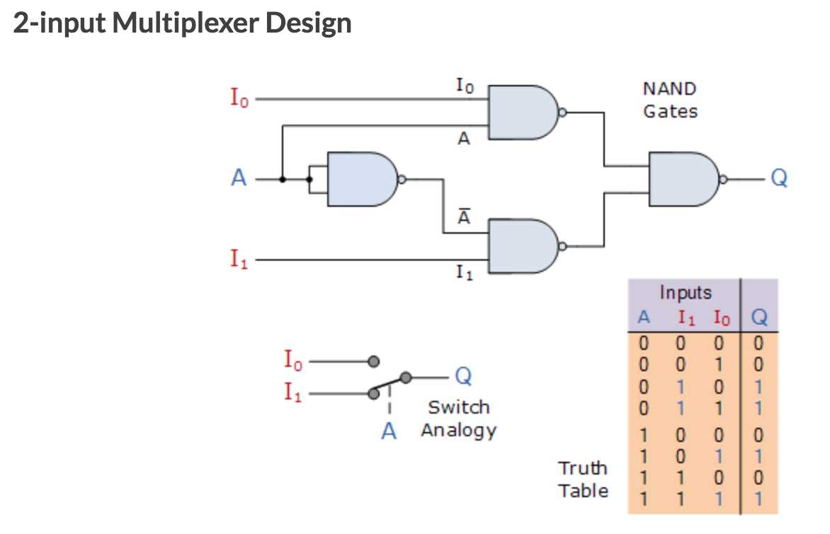
A 4 to 1 multiplexer is a combinational circuit that has four input lines and one output line. It selects one of the four input lines and transmits the corresponding data to the output line based on the selectors.
The working principle of a 4 to 1 multiplexer is based on the use of logic gates and selectors. The four input lines are connected to the logic gates (usually AND gates), and the output of these gates is connected to the input of an OR gate. The selectors (usually two select lines) determine which input line is selected. The output of the multiplexer is determined by the combination of the inputs and the selectors.
When the selectors are set to 00, the first input line is selected. When the selectors are set to 01, the second input line is selected. When the selectors are set to 10, the third input line is selected. When the selectors are set to 11, the fourth input line is selected. The selected input line is then transmitted to the output line through the OR gate.
The 4 to 1 multiplexer can be represented by a truth table, which shows the output for every possible combination of inputs and selectors. The truth table can be used to design the circuit and verify its functionality.
Construction of a 4 to 1 Multiplexer Circuit Diagram
A multiplexer, also known as a data selector, is a digital circuit that selects one of several input signals and forwards it to a single output line. The 4 to 1 multiplexer is a specific type of multiplexer that has four input lines and one output line. In this article, we will discuss the construction of a 4 to 1 multiplexer circuit diagram.
The 4 to 1 multiplexer consists of four input channels, denoted as A0, A1, A2, and A3, and one output channel, denoted as Y. It also has two control signals, denoted as S0 and S1, which are used to select the input line that is forwarded to the output. The truth table for the 4 to 1 multiplexer is as follows:
| S1 | S0 | A3 | A2 | A1 | A0 | Y |
|---|---|---|---|---|---|---|
| 0 | 0 | 0 | 0 | 0 | 1 | Y = A0 |
| 0 | 1 | 0 | 0 | 1 | 0 | Y = A1 |
| 1 | 0 | 0 | 1 | 0 | 0 | Y = A2 |
| 1 | 1 | 1 | 0 | 0 | 0 | Y = A3 |
To construct a 4 to 1 multiplexer circuit diagram, we need to use logic gates such as AND gates, OR gates, and NOT gates. The inputs A0, A1, A2, and A3 are connected to the inputs of the AND gates, while the control signals S0 and S1 are connected to the inputs of the NOT gates. The outputs of the AND gates are connected to the inputs of the OR gate, and the output of the OR gate is connected to the output channel Y.
By setting the control signals S0 and S1 to the desired values, we can select which input line is forwarded to the output. For example, if we set S0 = 0 and S1 = 1, the output will be equal to A1. Similarly, by changing the values of S0 and S1, we can select the other input lines.
In conclusion, the construction of a 4 to 1 multiplexer circuit diagram involves using logic gates to control the selection of input lines and forwarding the selected input to the output. This circuit is widely used in digital systems to route and control data signals.
Applications of 4 to 1 Multiplexer
A 4 to 1 multiplexer is a versatile digital electronic device that can be used in various applications. Some of the common applications of a 4 to 1 multiplexer are:
- Data Routing: A 4 to 1 multiplexer can be used to route data from multiple sources to a single destination. The selection lines of the multiplexer can be used to select which input data source to forward to the output.
- Data Selection: In Boolean logic and digital circuit designs, a 4 to 1 multiplexer can be used to select a specific data input based on the control signals or selection lines. This is useful in scenarios where multiple input options are available, but only one option needs to be selected at a time.
- Arithmetic Functions: A 4 to 1 multiplexer can be employed in arithmetic circuits to perform various mathematical operations. For example, it can be used to select the carry-in (Cin) input in addition circuits or the borrow-in (Bin) input in subtraction circuits.
- Logic Function Implementations: A 4 to 1 multiplexer can be utilized to implement logical functions such as AND, OR, NAND, NOR, etc. by appropriately connecting the input lines and using the selection lines to control the operation.
- Data Compression and Decompression: 4 to 1 multiplexers can be used in data compression and decompression algorithms. They can help in reducing the size of data by selecting the most significant bits or decompressing the data by selecting the appropriate bits based on the decoding algorithm.
In conclusion, a 4 to 1 multiplexer has various applications in the field of digital electronics. It can be used for data routing, data selection, arithmetic functions, logic function implementations, and data compression/decompression. Its versatility and flexibility make it an essential component in many electronic circuits and systems.