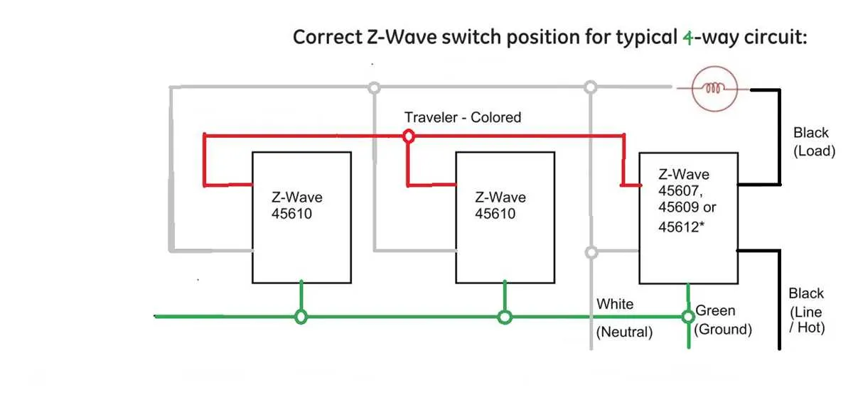
For seamless control of a lighting system from four different locations, use a configuration involving two intermediate toggles paired with two standard on/off units. This arrangement enables flexible management without complex rewiring.
Essential components include two three-terminal controllers positioned between the primary on/off devices. Ensure these are correctly oriented to maintain consistent current flow and prevent flickering or circuit failures.
When assembling the connection, prioritize the continuity of traveler conductors between all points. Label each conductor clearly to avoid cross-connection and to simplify troubleshooting. Employ insulated connectors rated for household current loads to enhance safety and durability.
4-Control Circuit Connection Layout
Use two intermediate toggles between two standard single-pole units to control a single light source from four separate points. Begin by connecting the live feed to the common terminal of the first single-pole lever. Link traveler wires from the first single-pole terminals to the inputs of both intermediate toggles. From the outputs of the intermediate units, run travelers to the inputs of the last single-pole toggle. Finally, connect the common terminal of the final single-pole device to the load.
Ensure traveler cables are insulated and routed carefully to avoid short circuits. Utilize color-coded conductors to distinguish between travelers and commons for easier troubleshooting. Employ a neutral conductor directly to the fixture, bypassing the control devices entirely. Confirm that all connections are secure and terminals tightened to manufacturer specifications to prevent loose contacts.
For optimal performance, use intermediate toggles rated for the circuit load, commonly 15 or 20 amps depending on the lighting system. Test the entire network by toggling each unit independently to verify the lamp switches on or off from every location. Implement a conduit system if wiring length exceeds recommended limits to protect cables and maintain electrical code compliance.
How to Identify and Prepare Circuitry for 4-Switch Installation

Start by turning off the power at the circuit breaker to ensure safety during installation. Verify this by testing the voltage with a non-contact voltage tester.
Next, locate the existing power source and understand how it connects to the light fixture and the controlling devices. Typically, you’ll find two traveler terminals, a common terminal, and a ground terminal in the current configuration.
For proper preparation, follow these steps:
- Identify the common terminal in the existing setup. This is usually where the incoming power cable is connected.
- Label each wire to avoid confusion. Use colored tape to mark wires according to their function (e.g., red for travelers, black for common).
- Ensure that all wiring is in good condition with no exposed copper or fraying. Replace any damaged sections before proceeding.
After the wires are identified, prepare your new components. You’ll need at least four terminals per device, and ensure that each terminal has a secure grip for each wire connection.
Check the gauge of your cables. If it’s smaller than 12 gauge, upgrade to a heavier gauge to ensure proper current flow and reduce the risk of overheating.
Next, make sure to use the correct screws or terminals to secure the wires, ensuring a tight connection. Loose connections can lead to unreliable operation or even electrical hazards.
Finally, plan the path for each wire, considering ease of access and safety. Never route cables through damp areas or near sources of heat. If necessary, use cable protectors or conduits for additional safety.
Step-by-Step Process for Connecting 3 or More Switches
To connect multiple controls to one light fixture, begin by identifying the power source and the wire connections needed for the circuit. First, ensure that the power is turned off before starting the installation. You will need at least one traveler wire for each additional control, along with a common wire for the power or fixture connection.
Start by connecting the first terminal of the power source to the common terminal of the first device. From this device, run two traveler wires to the next control. For each subsequent unit, connect the two traveler wires to their respective terminals on the device. The common terminal of the last unit should be connected directly to the light or fixture, ensuring the current flows through the circuit when activated.
Carefully secure all connections using wire nuts, ensuring that the exposed wire ends do not touch one another. Double-check that all terminals are properly tightened and that each wire is securely in place. Once everything is connected, turn the power back on and test the setup to verify that each control works as intended.
For safety, always use wires that are rated for the voltage of your system, and ensure that the wire gauge matches the specifications required for the circuit. Additionally, consider labeling each control for easy identification during future maintenance or modifications.
Troubleshooting Common Electrical Issues in Multi-Switch Circuits

Start by ensuring all connections are secure. Loose wires often cause intermittent or non-functional setups. Check that all terminal screws are tightly fastened, especially on the traveler terminals and the common terminal of each device.
Verify proper wire connections. Miswiring is a common problem, especially when using multiple control points. Confirm that each wire is connected to the correct terminal: the common terminal should always connect to the power source or light, and the traveler wires should alternate between devices.
Test for power at each control point. If one of the devices is not working, use a voltage tester to check for current flow. If no voltage is present at the common terminal, there may be an issue upstream, such as a tripped breaker or faulty wiring between devices.
Inspect the devices themselves. A malfunctioning or worn-out component can also cause problems. Replace any damaged devices, such as faulty pushbuttons or contacts that may not be engaging properly.
Ensure the correct wire gauge is used. Using an undersized wire for the current load can lead to heating issues, increasing the risk of failure. Always use wires rated for the electrical load to prevent potential hazards.
Check for any short circuits. A short can occur when wires touch each other, often due to damaged insulation or incorrect installation. A short will typically cause a breaker to trip or prevent the system from operating correctly. Inspect the entire circuit for any exposed or damaged wiring.