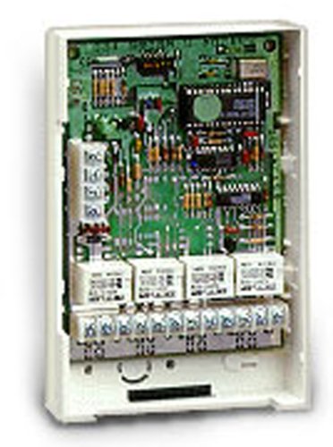
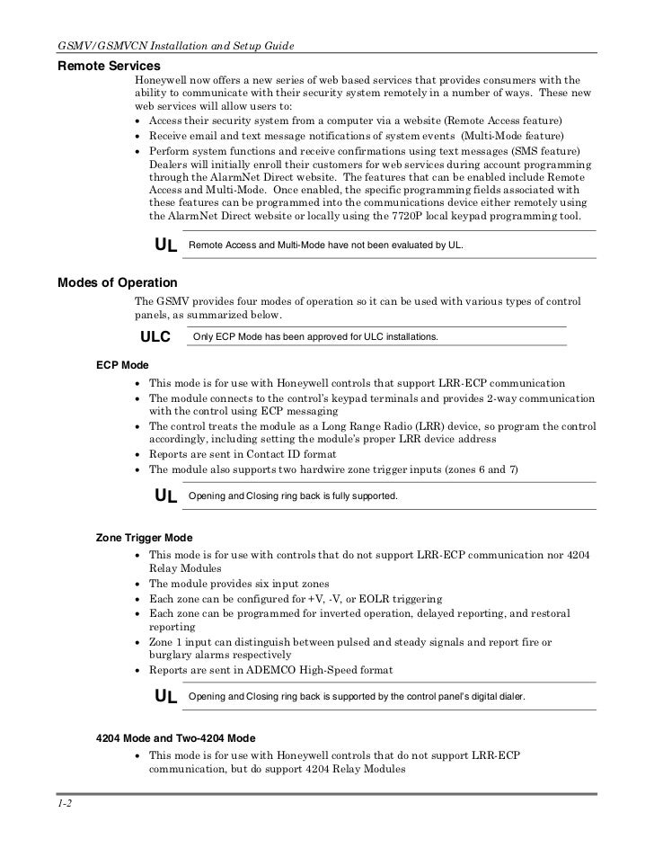
The ADEMCO Relay Module adds from one to See the control’s instructions for additional installation instructions for specific information on how.
I was staring at the manual some more and I think I figured out how to connect the smokes to the relay. I connected the red wire of the.
The ADEMCO Relay Module adds from one to See the control’s instructions for additional installation instructions for specific information on how. I was staring at the manual some more and I think I figured out how to connect the smokes to the relay. I connected the red wire of the.
4th Make sure module’s DIP switches are set to the selected address. 9.
( See instructions for zone list programming, we will not cover this in this.can be done either via the control’s auxiliary relay (if supported) or through a relay on a relay module. Wire the common of the relay to 12VDC and the N.C. contact on the U (TB2, terminal 3).
The relay you use must be programmed for “Smoke Protector Reset” (see control panel’s instructions). peripheral devices.
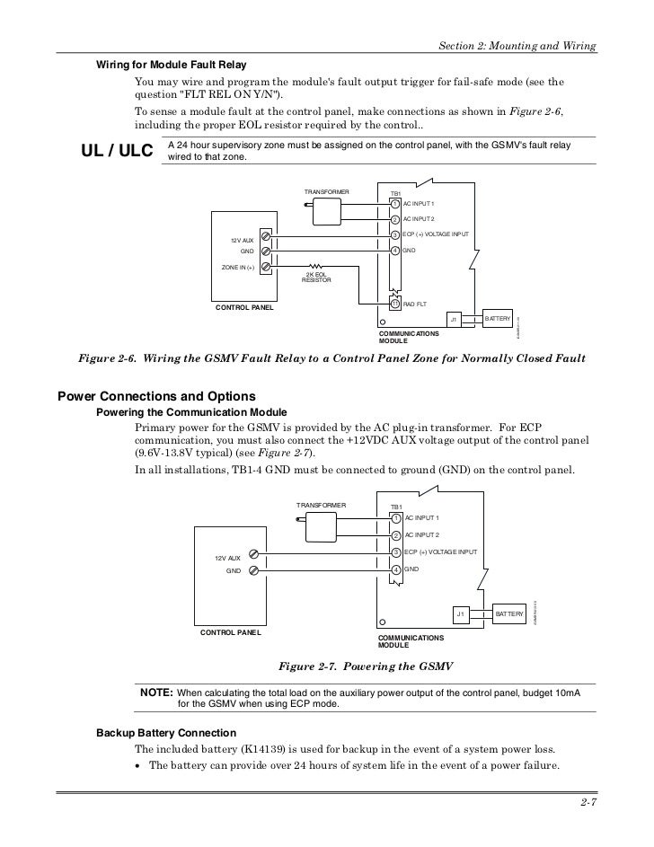
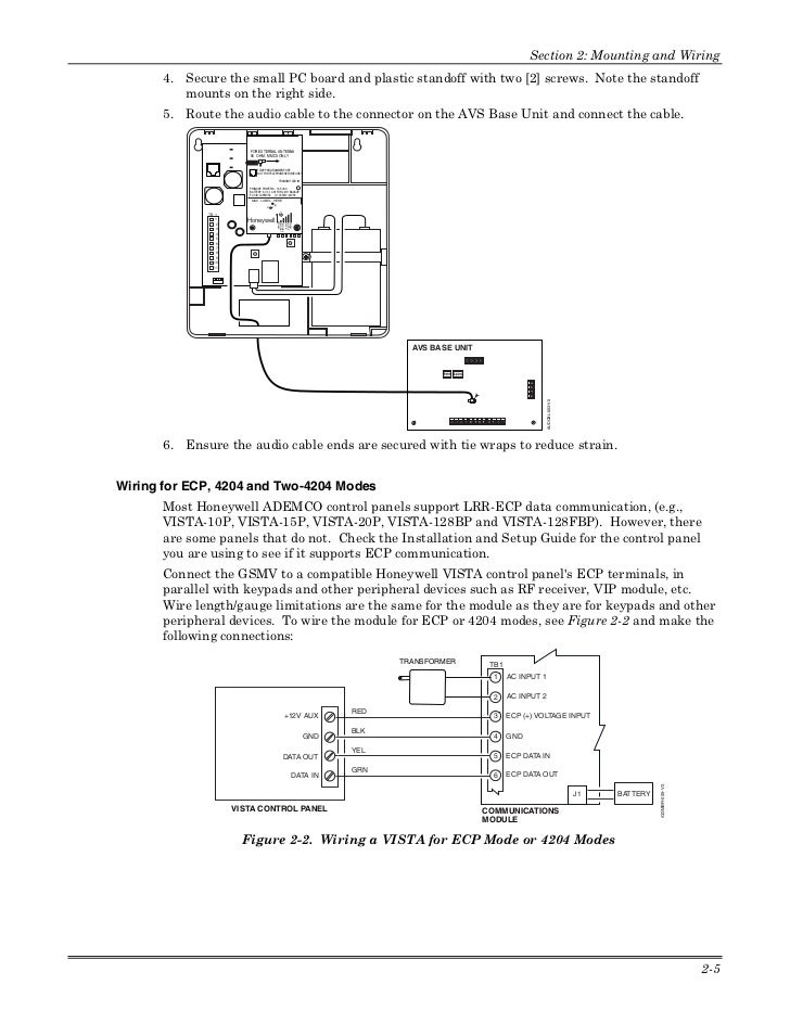
To wire the module for ECP or modes, see Figure 2 and make the following connections: Table 1. Wiring connections for ECP or modes GSM Control Terminal 3 V+ +12 V Aux Terminal 4 GND Ground Terminal 5 Data In Data Out Terminal 6 Data Out Data In GSM VISTA CONTROL PANEL GSMV0 GND ECP DATA OUT ECP DATA IN.
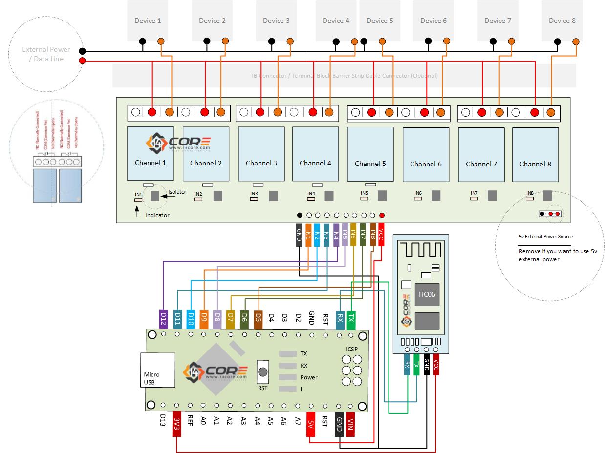
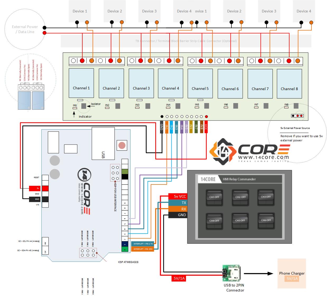
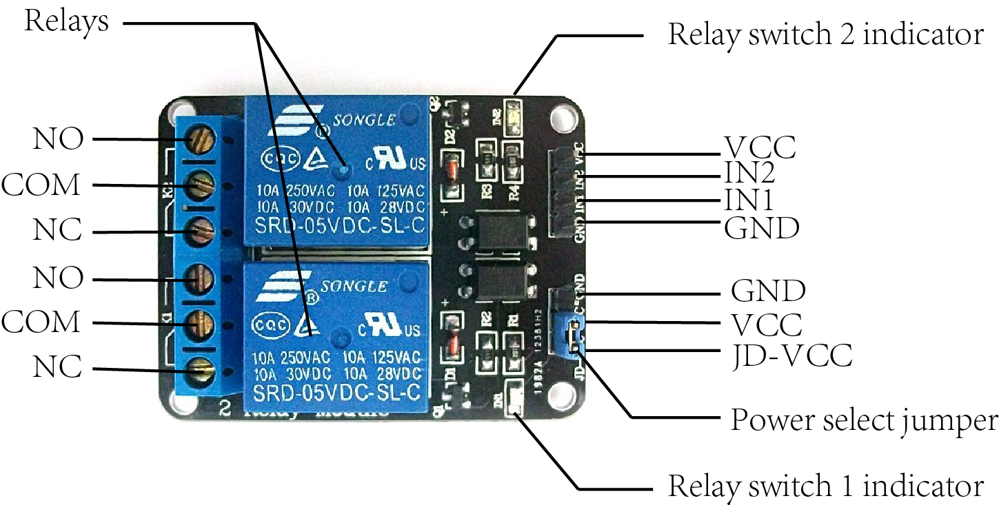
Wiring 8 Channel Optocoupler Relay Module In this tutorial we will going to wire the 8 channel Relay Module driven by our own very owned microcontroller, the below illustration illustrate 8 device on external power source triggered by the relay. using a No, Relay Module.
A No. AD or Alpha Console is required for programming zonea and relay ~peration, but it need not remain in the system. These consoles have digital keypads and 2-line 32 character alphanumeric LCDS (Liquid Crystal Displays).
Programmed options to establish specific alarm and re-. The PCCX is a Power Supply/Relay Output/ Combus Repeater Module. The PCCX provides a power output for system devices, 4 programmable relay outputs and an output to regenerate the Combus data signal to allow for longer wire runs.
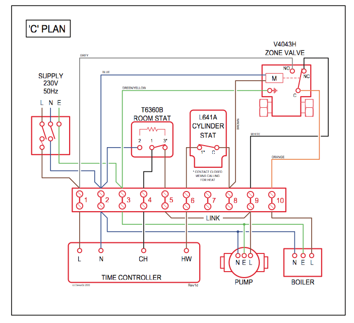
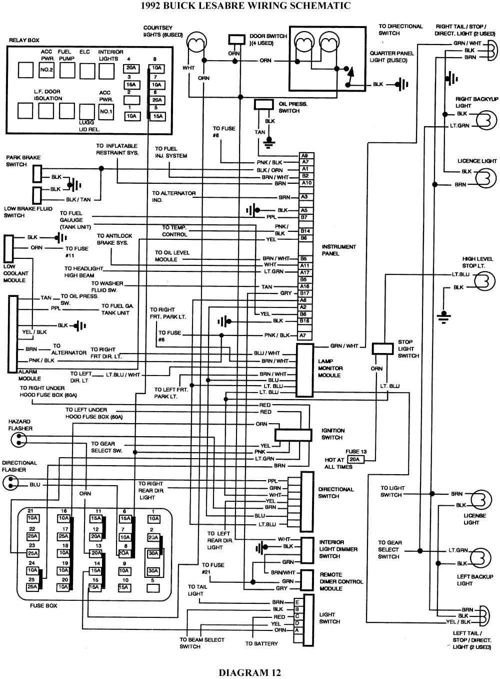
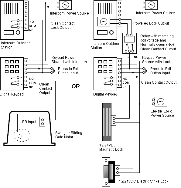
NOTE: Do not use any power supply other than the PCCX to repower the Combus.Ademco: Ademco Relay BoardDoor Locks – 5 Wire Alternating 12 Volts Positive (Type C) Relay Wiring Diagram