manual and magnetic across-the-line starters may be applied. ..
Reversing. Starter.
Bulletin. RS. Sizes 0 & 1.
3 Phase. 2 Phase, 3 Wire.
Two-Speed. Starter.
Thermal. Magnetic. Single Phase.
3-Phase. Squirrel Cage. 2-Phase, 4-Wire.
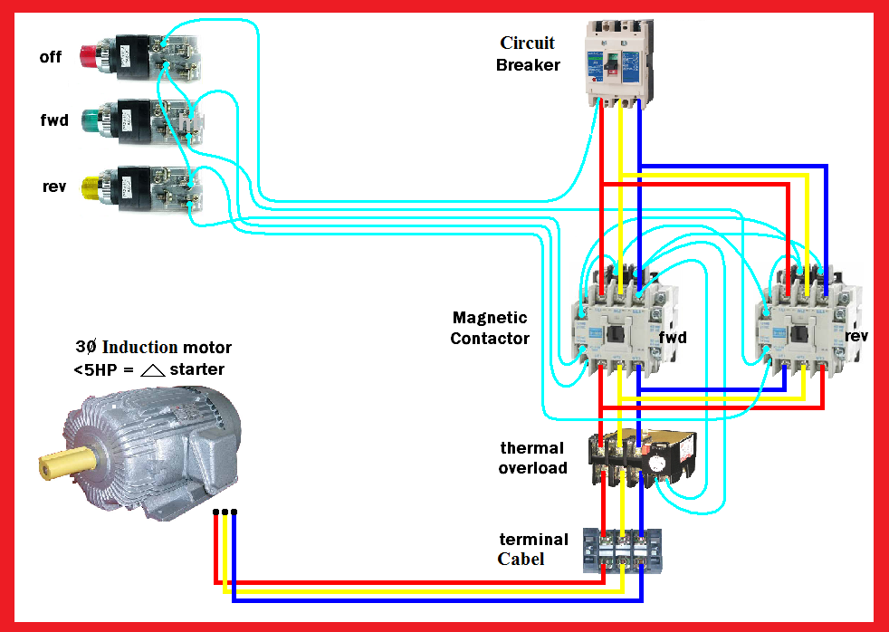
Wound Rotor .. 3-Wire Control: Reversing Starter w/ Pilot Lights to.
Indicate Motor. Wiring Diagrams.
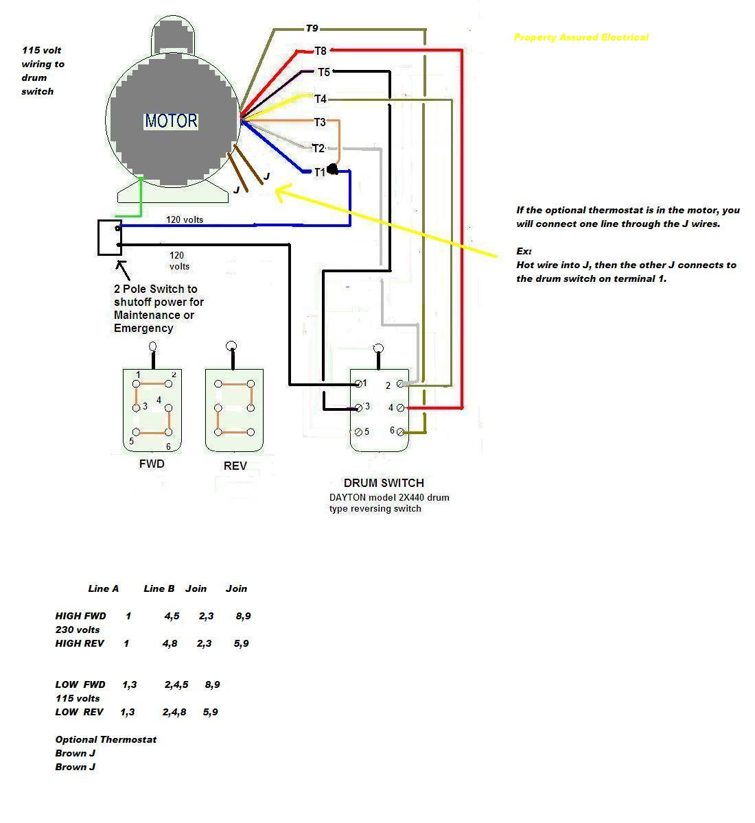
ALWAYS USE WIRING DIAGRAM SUPPLIED ON MOTOR NAMEPLATE. – colored leads are only applicable on the NEW ROLLED STEEL motor lines – Single Voltage / Reversible Rotation.
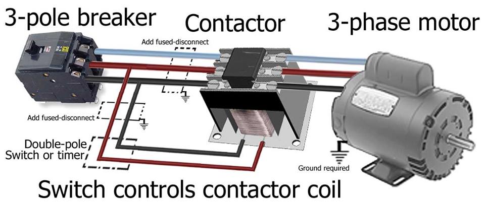
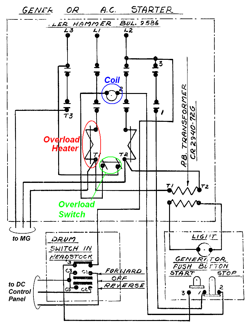
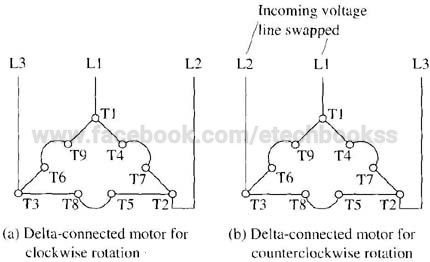
Dual Voltage / Single Rotation. When a Double/Triple Pole manual motor starter is turned off, the power from Three Phase motors require 3 pole starters and each of the “hot” lines coil as auxiliary circuit – as shown in the motor reversing diagram as coil.
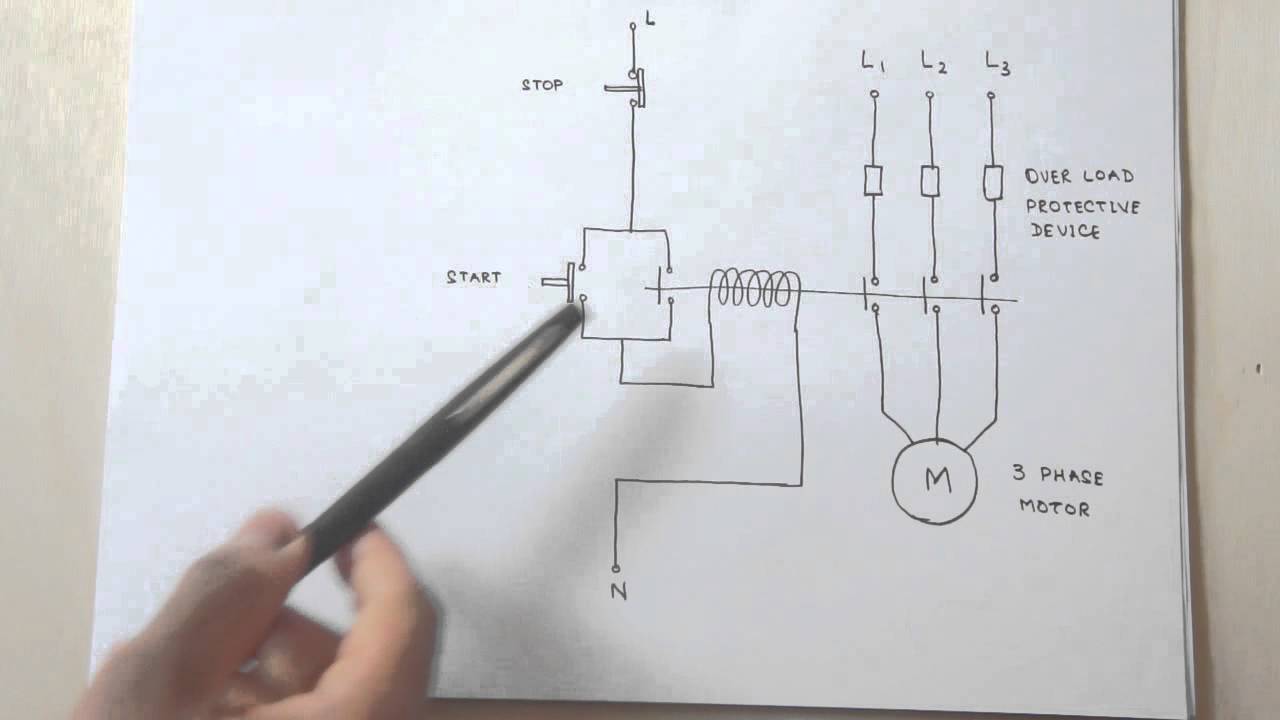
Hand Off Auto · Enclosed Motor Starter Control Panel Start Stop · Enclosed Reversing Motor Starter .. The most common use of 3 wire control is a Start/Stop control. relay energizes and it pulls in the R1 contactor that feeds three phase power to the motor.
Use the top diagram to help you figure out how to wire it.Line Voltage Control three phase (3ph) motor starter controlling a three phase motor (rev 08 Aug ) The above wiring diagram assumes your magnetic starter has a V coil. If you have a V coil, instead of running a line from Coil – Overload – L2, you must run Coil – Overload – Neutral.
Three-Phase Wiring Diagrams ALWAYS USE WIRING DIAGRAM SUPPLIED ON MOTOR NAMEPLATE – colored leads are only applicable on the NEW ROLLED STEEL motor lines – Single-Phase Wiring Diagrams Capacitor Motor Single-Phase Wiring Diagrams ALWAYS USE WIRING DIAGRAM SUPPLIED ON MOTOR NAMEPLATE. There is a wiring diagram and knock-outs for adding pushbuttons, pilot lights, etc.
Starter is size 1. Enclosure is Nema 3R. This is not a combo starter, you will need a separate disconnect.
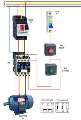
Fig. 3: Simplified GN0 Motor-Reversing SSR wiring diagram As can be seen from figure 3 above, two of the three phases are wired through the GN0 and the third phase is connected directly to the motor. When a logic signal is applied to the “forward” terminal, the GN0 switches L1 and L2 directly to . 3 Phase or 2 Phase, 3 Wire (For 2 Phase, 3 Wire, L2 and T2 are common) Sgl. Phase Lines Sizes 0,l and 1P Single Phase Sizes and 1 Direct Current 6 Pilot Light Red Black Sizes 0 & 1 3 Phase With Pilot Light 8.AC Motor Control Circuits | AC Electric Circuits WorksheetsReversing Motor Starter | eBay
