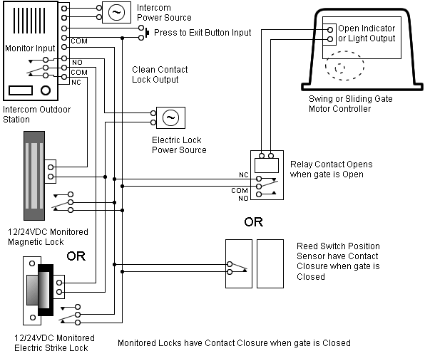
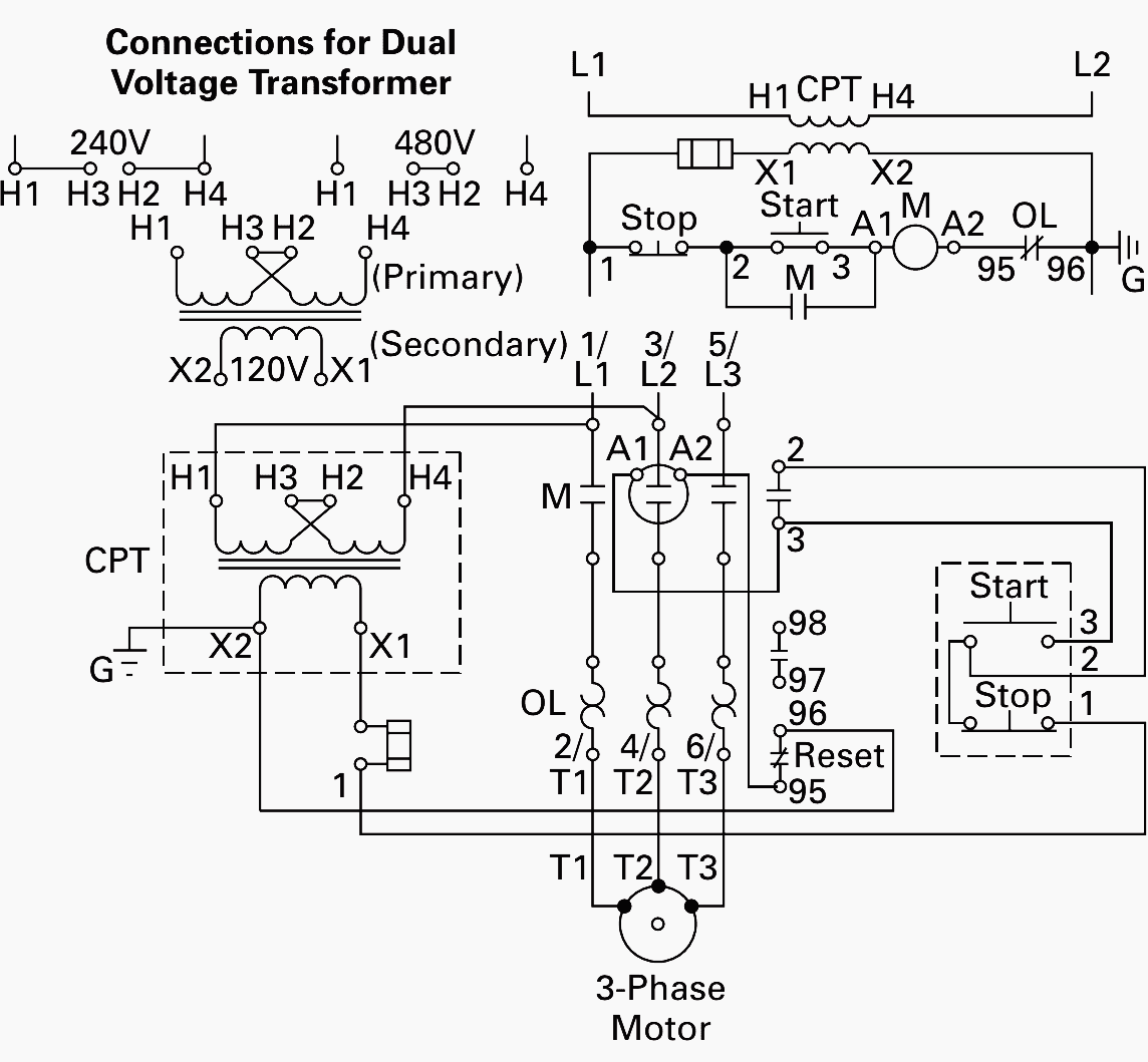
Why use a Control Power Transformer? The schematic symbol for the transformer is represented by two groups the main motor circuit operates at V, while the control circuit is at V. Control Circuit Wiring of CPTs.
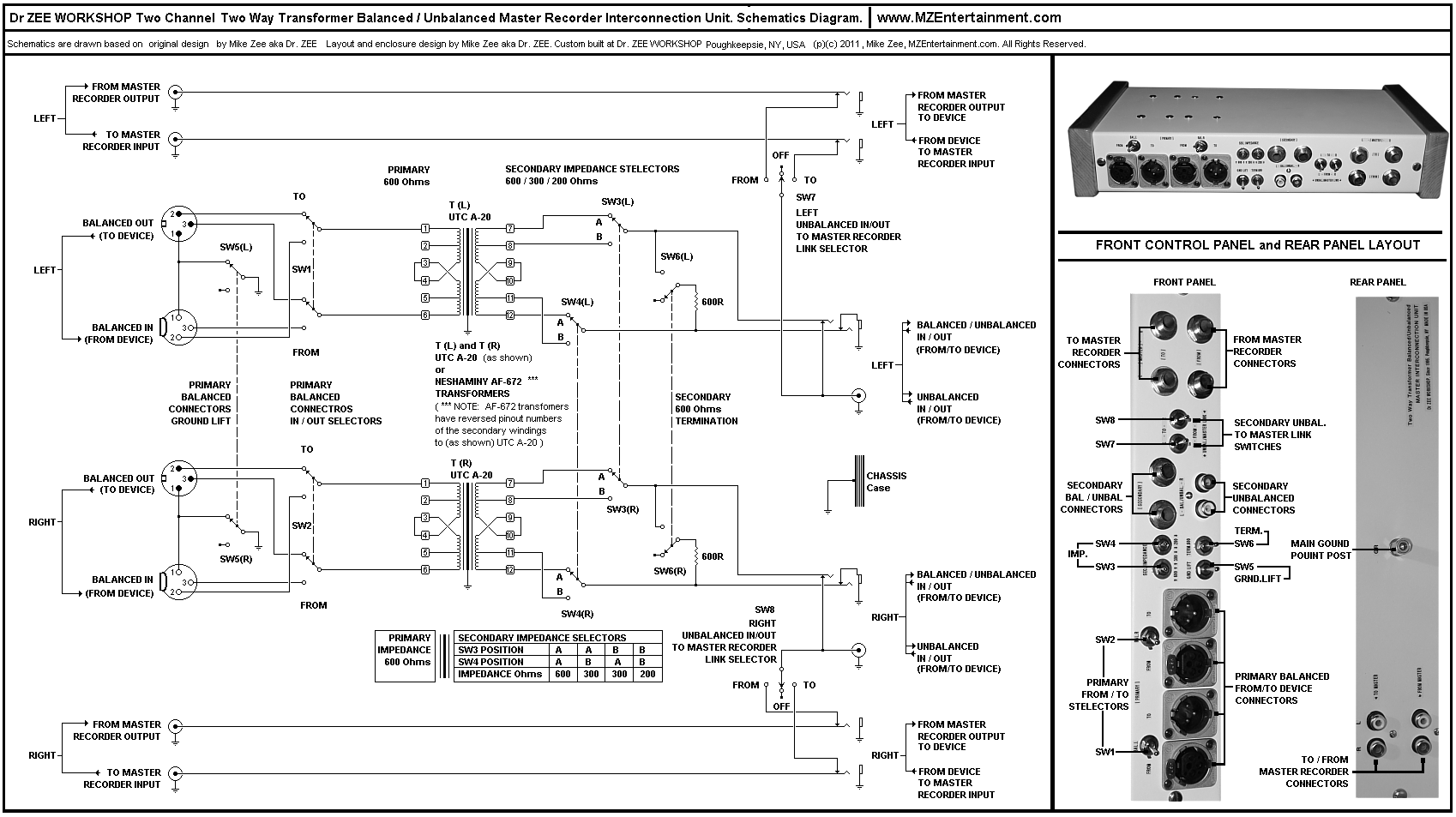
I have a control transformer which has v 3 phase primaryv single phase secondary. For some reason, the wiring diagram doesn’t make.
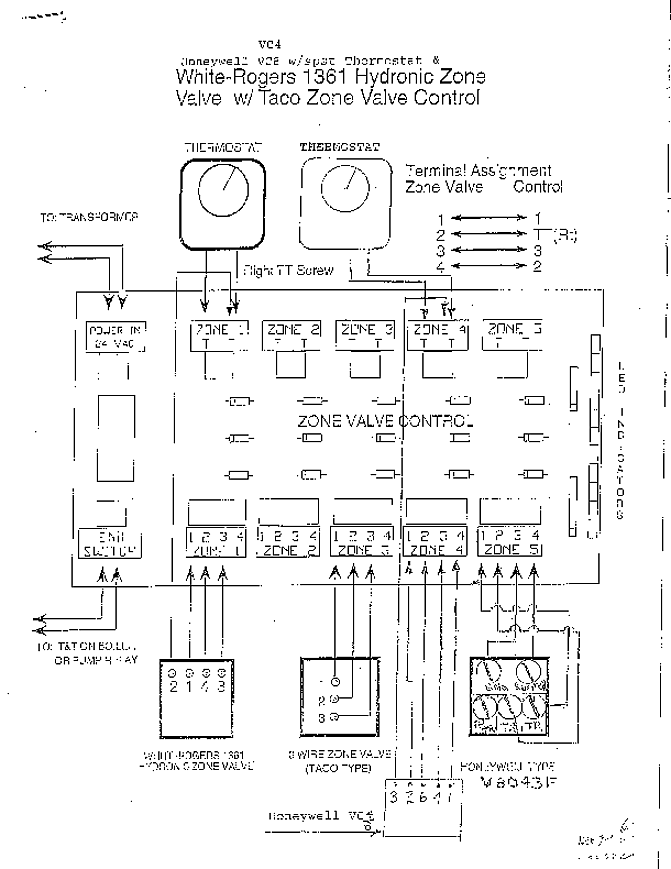
In transfomer below, I presume I can achieve volt input and get both and output, yes? Thread: input / output control transformer wiring mystery The only reason the wiring diagram is so specific about the if you get the two V secondary windings in parallel and out of phase. A control transformer is an isolation transformer designed to provide a high degree of secondary voltage ..
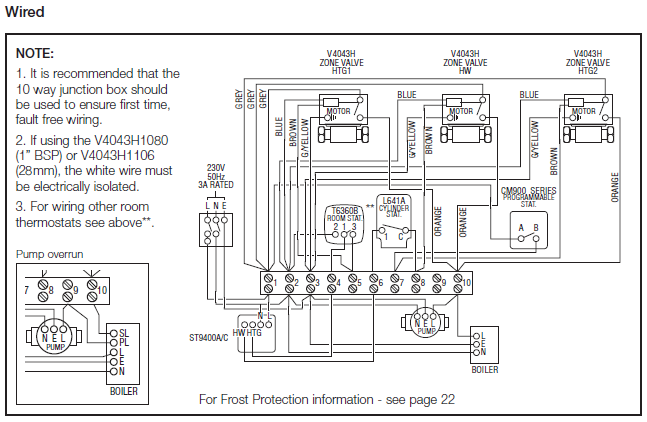
Refer to page 52 for wiring schematic drawing. If you have any questions regarding these wiring diagrams or are having any difficulty V.
V. V.
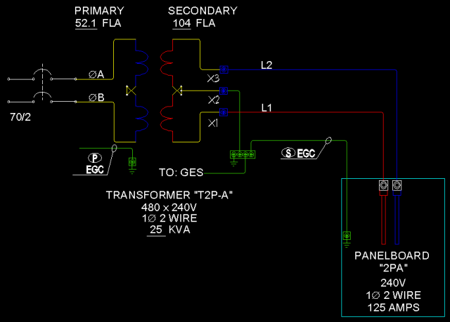
V. PH***AJ Schematic for 50, 75 and VA Units ..
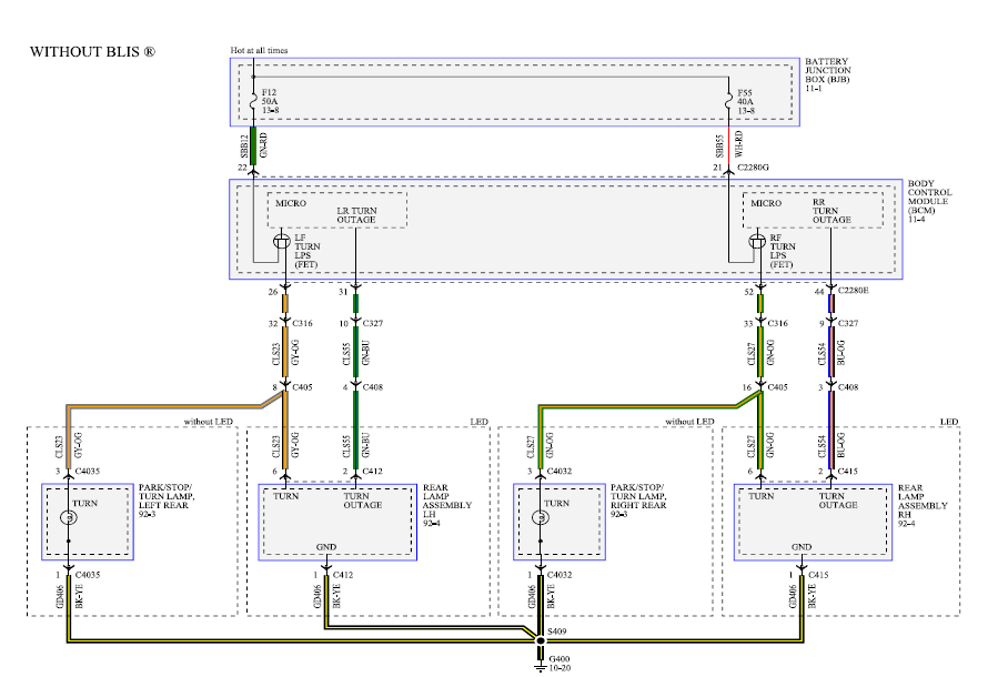
21 3 4. HV. 5 6 21 3 4 5 6. V.
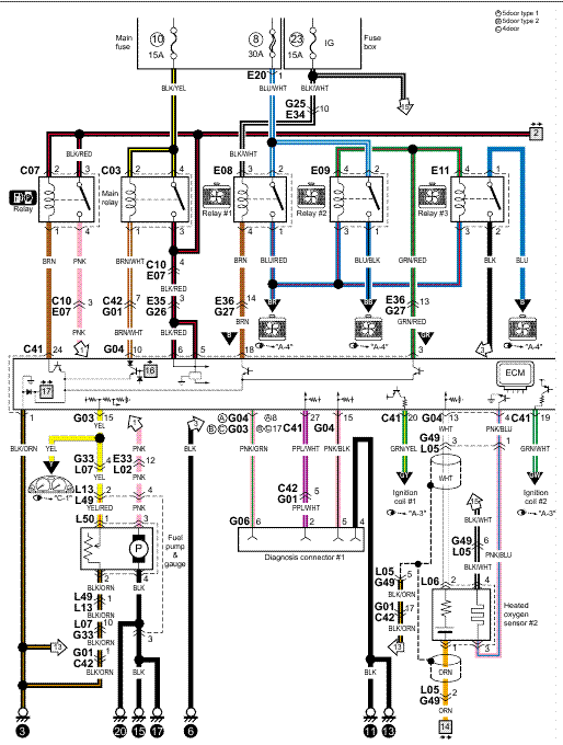
V. V.
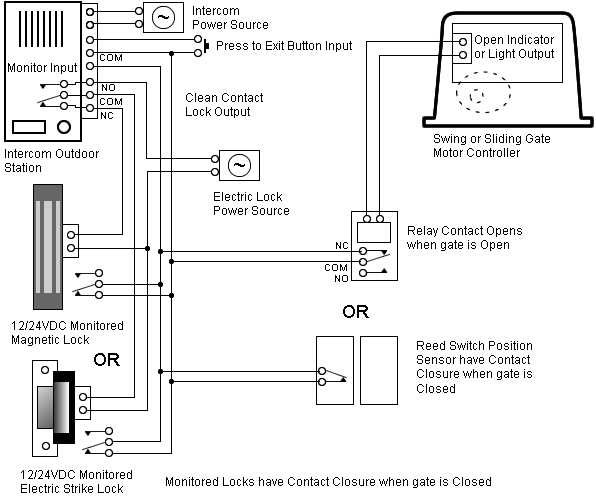
V. V. V.
V. 23V.Collection of step down transformer v to v wiring diagram.
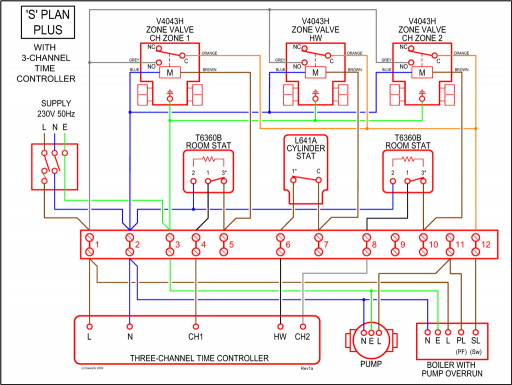
A wiring diagram is a streamlined standard pictorial depiction of an electrical circuit. ELECTRICAL DATA WIRING DIAGRAMS V, V V AC OR DC SINGLE PHASE L1 L2 One or more heaters in parallel, single phase.
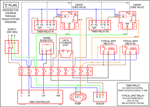
ACB L1 L2 V, V AC OR DC SINGLE /V TRANSFORMER ACB CONTROL CONTROL One or more heaters in parallel on V 3 phase circuit. Jan 04, · I have had this transformer since and it’s been in storage for almost 5 years- next time we’ll get the //Volt transformer and see what it does.
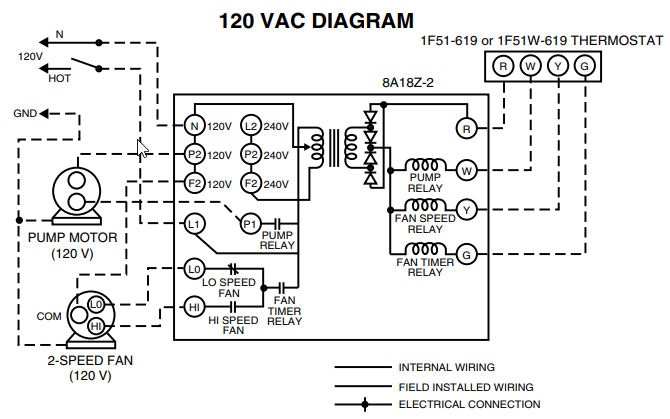
3 Phase Transformer Wiring Diagram Three Pdf With V To V. Step Down Transformer v To v Wiring Diagram How Hook Up A In V V.
v To v Transformer Wiring Diagram In V V. Control Transformer Wiring Diagram v To v New V V. General Purpose Transformers Energy efficient dry-type transformers Volt Class, isolation type, single and three phase, 15 kVA through kVA.
Indoor and outdoor models available.v/3P v1P transformer wiring confusionFresh v to v Transformer Wiring Diagram – Diagram | Diagram