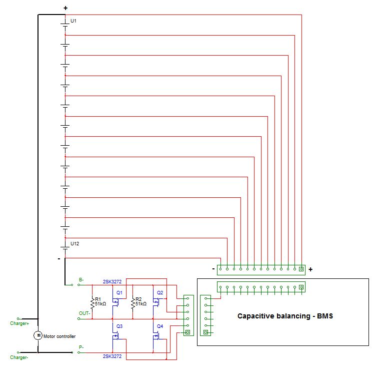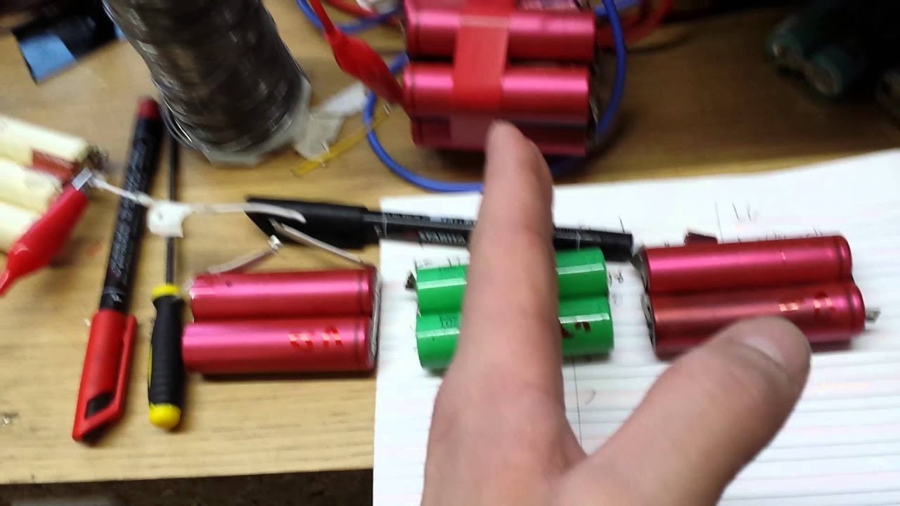
A subreddit for practical electronic engineering questions: Circuit and ..
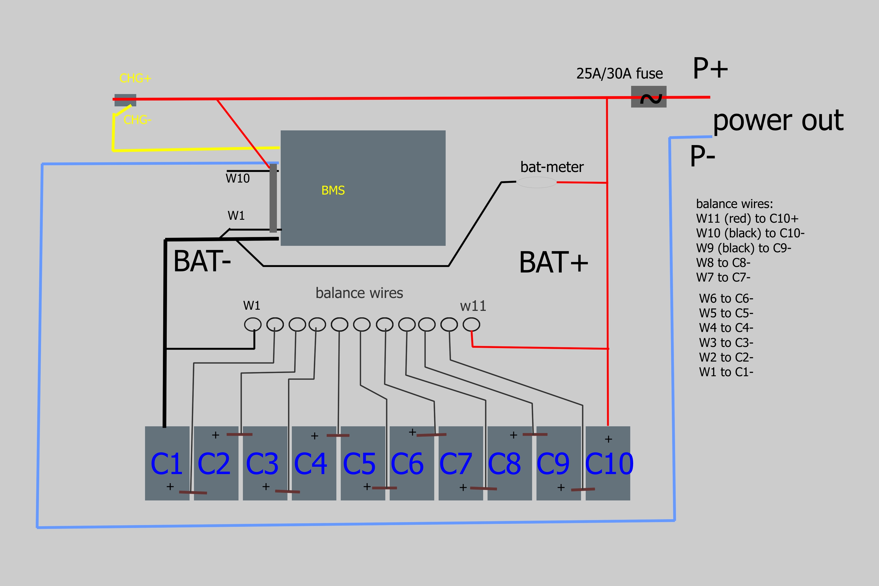
Okay let me throw in an image of the schematic I was thinking of. .
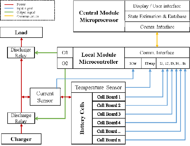
5P4S has 3 intermediate nodes (1 BMS); 4S5P has 12 intermediate nodes (requires. That BMS looks identical to one that I’ve used and it does NOT do balancing or proper charging.
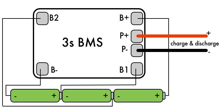
Just protecting from over current, over voltage. Is the best solution to solder both cables to the BMS or to solder one and I have updated my BMS wiring diagram to match the pad and pin. I bought this BMS from ebay (schematron.org?_t EBIDX%3AIT), but I don’t know how to connect them to my 13s10p.
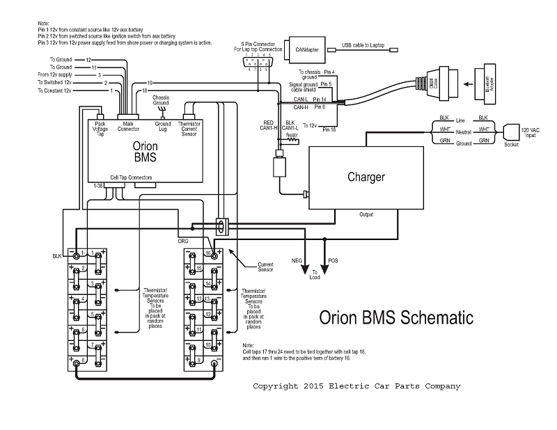
Make sure to consult the wiring diagram for your BMS, because some BMS’s have one more sense wire than cells (for example, 11 sense wires for a 10S pack ).DISCLAIMER: This wiring diagram generator is intended to be used as a guide for connecting an Orion BMS to a battery pack. Since there may be wiring considerations that this tool cannot anticipate, always read through the full wiring manual and verify the diagram before wiring the battery pack.
Building Management Systems – Installation Guide. FFI Actuator & Control Systems PSIB accessory can be used in many instances; it is used more often when there are 2 or more RQ’s.
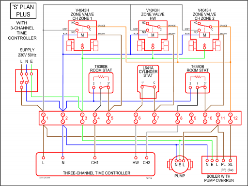
Diagram elements are not to scale. Example: Building Management System layout diagram. For reference only – not project specific.
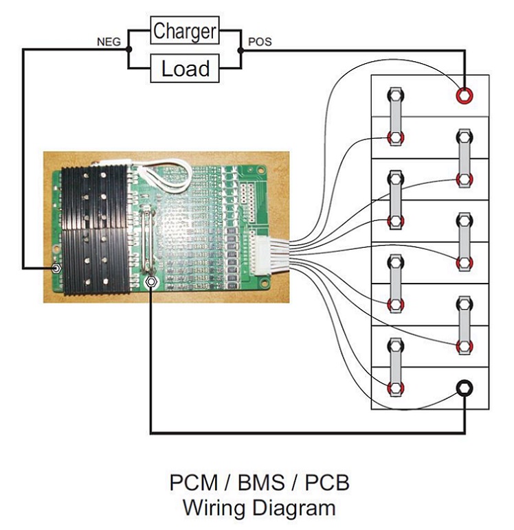
Building Management System s. Bms Wiring Diagram – Wiring Diagram And Schematics Help with 6S2P with BMS wiring Endless Sphere Source · 10s4p BMS byp jpgx KB. BMS Heritage cc Wiring Diagram – Wiring Diagrams – Dan’s Garage Talk BMS_Heritage_JPG.
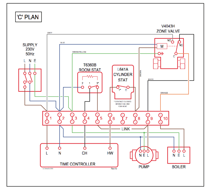
Congratulations on your purchase of the Q3™ Building Management System! The Q3 is open contacts available for controlling low voltage pilot duty relays using Class 2 wiring.
A 16th output is provided with normally open and normally closed contacts. Each relay is rated for 1 amp at 30V AC or DC. The following basic wiring diagrams show how batteries, battery switches, and Automatic Charging Relays are wired together from a simple single battery / single engine configuration to a two engine, one generator, and four battery bank system.Diy 4s battery pack [How to charge, how to build?] – Page 2Battery Management Wiring Schematics for Typical Applications – Blue Sea Systems
