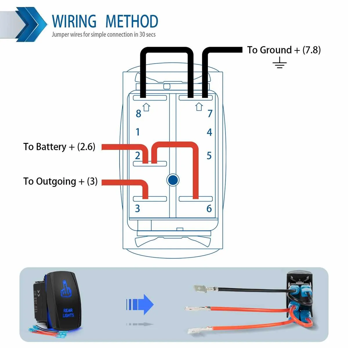
When working with a 5-terminal toggle control, it’s crucial to understand the proper way to route the connections for reliable performance. The first step involves identifying the terminals: typically, two are used for input, two for output, and one serves as the common ground. The key to success here is ensuring correct placement of wires, as incorrect wiring can result in malfunctions or even damage to the control and connected components.
To start, connect the power source to the designated input terminals. These should be clearly marked, often as “IN” or “L” for live. Next, the output terminals are typically marked as “OUT” or “T”. Ensure that the current flows through these terminals to the intended device. The central terminal, usually labeled as “C”, is essential for grounding the system and should be connected to the chassis or ground reference.
Remember, color-coding of wires plays a vital role in preventing confusion. Use distinct colors for each connection, with red commonly for positive connections, black for negative, and green for grounding. This helps maintain a clean and organized setup, especially when troubleshooting. Also, always double-check that your connections are secure to avoid any loose wires, which can cause unreliable operation.
Tip: When unsure of the terminal functions, consult the manufacturer’s manual or datasheet for your specific model. Each system may have slightly different layouts or features, so this step can prevent costly mistakes.
5-Terminal Toggle Control Connections
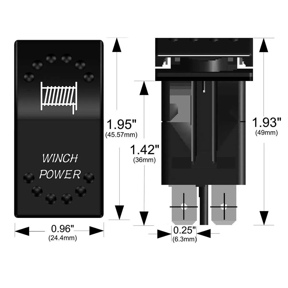
For proper functionality, connect the central terminal to the power supply input. The two outermost connections serve as outputs, directing current to your device or system. The remaining middle contacts are often used for auxiliary functions, such as controlling additional components or serving as a return path. Ensure the terminals are properly isolated to prevent short circuits, especially when working with high-power loads.
The terminals that handle output can be linked to different control devices, depending on the system you are implementing. It’s critical to match the voltage and current ratings of the terminal to your load requirements, to avoid overheating or damage. For safety, use a fuse between the power source and the device for protection against surges or faults.
In a typical setup, one of the auxiliary terminals will often connect to a ground or a neutral return, completing the circuit. This is a necessary step to ensure that the device operates with a stable and controlled flow of electricity. Always verify your connections with a multimeter before powering up the system to avoid accidental shorts or damage.
How to Connect a 5-Terminal Toggle for Basic On/Off Functionality
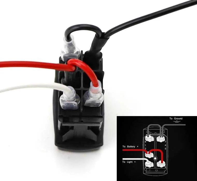
For a basic on/off operation, you will need to connect the terminals correctly to ensure the device works efficiently. Here’s the straightforward way to do it:
1. Identify the terminals: You will have five terminals: two for power input, one for output, and two for control. The terminals are typically labeled for easy identification. Refer to the manufacturer’s labeling to avoid confusion.
2. Power input connection: Connect the positive terminal of your power supply to one of the input terminals. The second input terminal should be connected to the negative side of the power supply. This establishes the base power connection.
3. Output connection: Connect the output terminal to the device that requires control. This will allow the flow of power to the device when activated.
4. Control terminals: The two remaining terminals are for toggling the device. One will be connected to the power input (positive) and the other to the output device. These terminals manage the on/off status of the connected load.
5. Testing: Once all connections are secure, test the setup by activating the toggle. The device should turn on when engaged and off when disengaged. Ensure no wires are touching or short-circuiting to prevent malfunction.
Note: Double-check each terminal to ensure proper connection, especially when setting up for simple on/off control. Incorrect wiring can lead to malfunction or damage to your components.
Connecting Auxiliary Circuits Using a 5 Pin Rocker Switch
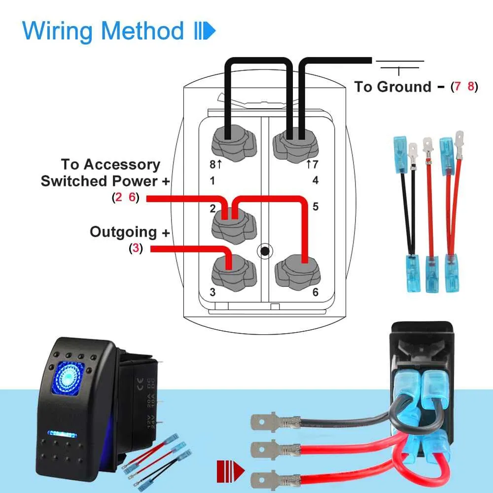
To integrate additional circuits effectively, follow this straightforward guide for connecting auxiliary devices using a 5-pin actuator.
- Step 1: Identify the Primary Contacts
The central terminals are used for the main control function. These provide power to the connected equipment and must be connected to the power source and load. Ensure correct polarity for safe operation. - Step 2: Integrate Auxiliary Components
The remaining contacts are designed to manage additional circuits. These can be linked to secondary devices like lights, fans, or other accessories. Use the appropriate relay or fuse for each auxiliary circuit to prevent overloads. - Step 3: Connection of Ground and Load
One terminal should always be connected to ground to complete the circuit. The corresponding terminal should link to the load side of your auxiliary device to complete the flow of electricity. - Step 4: Use Separate Power Lines for Each Circuit
Avoid running multiple high-power components through the same line. Each auxiliary function should have its own power wire, ensuring reliability and reducing the risk of interference or short circuits. - Step 5: Double-Check the Connections
Before finalizing, carefully inspect all connections. Ensure there is no loose wiring, short circuits, or misconnections between power and ground points.
By following these steps, you ensure safe and efficient operation of multiple auxiliary circuits through a single actuator. Always prioritize proper fuse ratings and verify load capacities to prevent damage.
Troubleshooting Common Issues with 5 Pin Rocker Switch Wiring
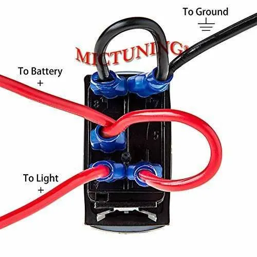
Check for proper connections first. Ensure that the terminals are securely attached and there are no loose wires or poor solder joints. A weak connection can cause intermittent operation or complete failure.
If the device doesn’t power on, verify the continuity of the circuit. Use a multimeter to check for open circuits and ensure the flow of current from the source to the intended load.
Overheating is often a result of a poor connection or excessive current draw. Ensure that the wire gauge is adequate for the load, and consider using a fuse for added protection if none is already in place.
If the component behaves erratically (flickering or switching between states), inspect the internal contacts. Wear or corrosion on these parts can cause inconsistent performance. Clean or replace as necessary.
In cases of unresponsiveness or failure to change states, check for short circuits or ground faults. Make sure the connection to ground is solid, and there is no unwanted path that might prevent the proper switching action.
Test the control device with an alternate unit if available. This helps identify whether the issue lies within the switch mechanism or somewhere else in the electrical setup.