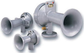
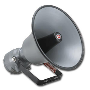
The Federal Signal Models 55 and 56 are electric horns that produce sound by means of Because the output is greater than that of a vibrating horn resonating. covered in the manual that ships with the control console.

Original . for Home), 9×56 pixels, 7-inch x inch active display area, capable of showing .. This scoreboard ships with a Federal Signal Model 55 Resonating Horn installed in the.

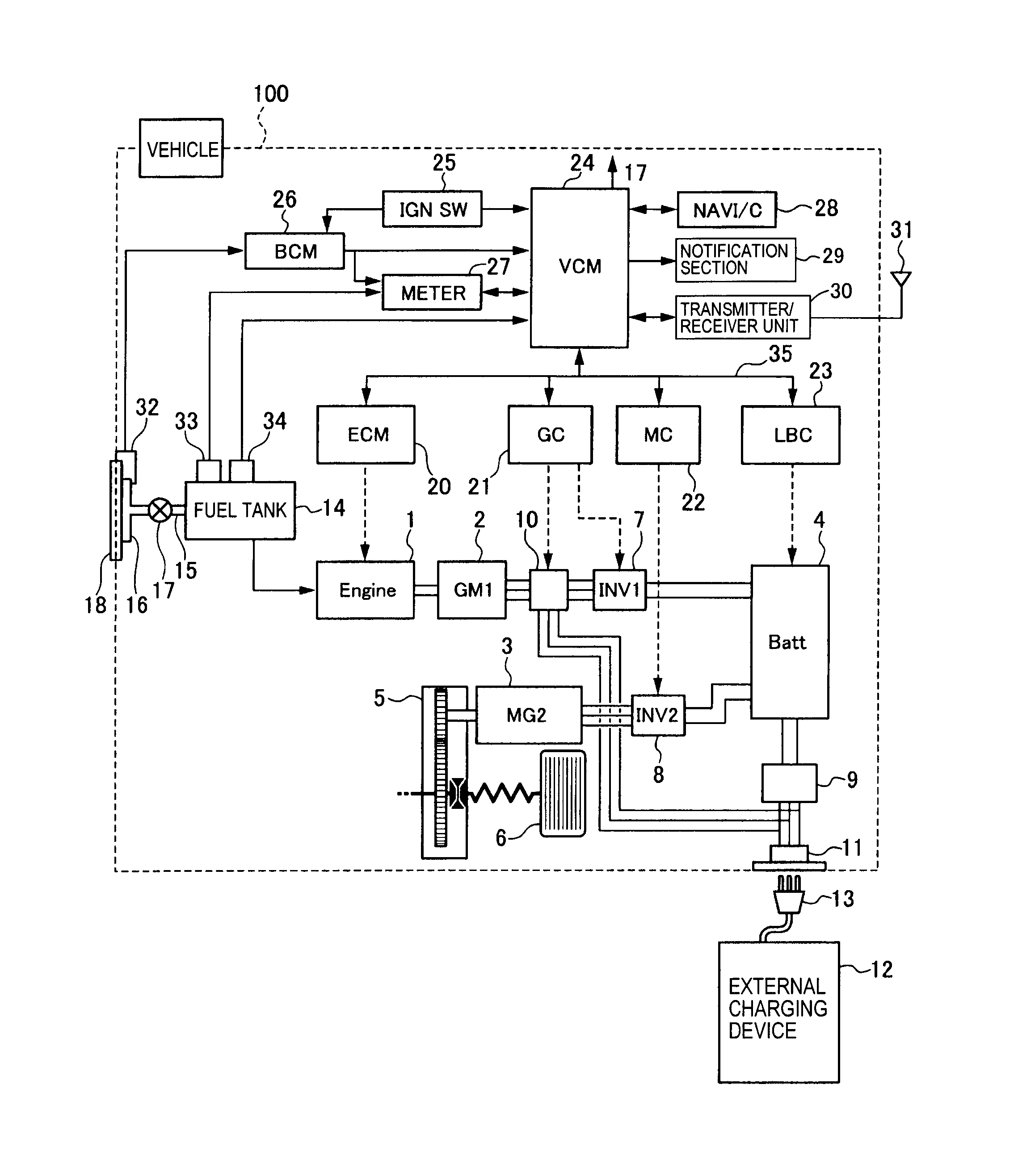
Looking for FEDERAL SIGNAL Resonating Horn, Continuous Sound Pattern, Federal Signal 55 1 Diagram · Federal Signal Safety & Security Systems. Multi-Tone Signals Multi-Tone Signals .. Federal Signal 52 Series Resonating Horn, 24 VDC, 4 A, / dB, Surface .
Edwards Signaling™ Adaptatone® MAQ Millennium Central Tone Generator, 55 Tones, 50/60 Hz Federal Signal 56 Series Electric Resonating Horn, VDC, A. The Federal Signal Models 55 and 56 are electric horns which produce sound by means of a diaphragm, which resonates a column of air.

Because the output is.Federal Signal 55 1 Diagram; Federal Signal Resonating Horn Sell Sheet; Federal Signal Resonating Horn Sell Sheet; Alternate Products. Alternate Products may not be identical in style or function to original selection. Please compare below for more information.
schematron.org: $ Signal wires 55 from the monitoring mechanism 44 are connected to the garage door opening mechanism As illustrated in FIG. 3B, the signal wires 55 are attached to the same posts 56 on a terminal strip 59 of the garage door opening mechanism 14 that wires 57 connecting the wall switch 36 to the garage door opening mechanism are connected to.

Resonated column of air generates sound Produces dBa @ 10′ (dBa @ 1m) Indoor/outdoor use FM Approved Model 55 (VAC) is UL Listed and CSA Certified The Federal Signal Models 55 and 56 are electric horns which produce sound by means of a diaphragm, which resonates a column of air. Because the output is greater than that of a vibrating horn resonating horns can be used wherever a .
The choke butterfly is located in this air horn. [2] It is also a term used for a warning horn which is operated by forcing compressed air through a reed. air horn baffle: Used on some Rochester Quadrajet carburetors to prevent incoming air from forcing fuel into the secondary wells through the bleed tubes.
If the direction signal is entirely inoperative, check the fuse (see wiring diagram) flasher unit and circuit from the fuse box up through the steering column switch in the order named. The flasher unit is located behind the facia panel below the face level vent on the driving side.55 Resonating Horn | Federal Signal DistributionAES E-Library » Complete Journal: Volume 2 Issue 1
