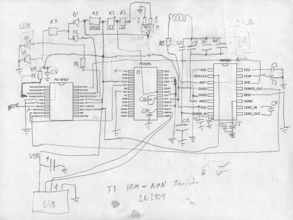
The 5F2 schematic is a classic amplifier design that has stood the test of time. It is known for its simplicity, versatility, and iconic tone. Originally introduced in the 1950s by Leo Fender for his line of amplifiers, the 5F2 has become a staple in the world of guitar amplification.
One of the defining features of the 5F2 schematic is its use of a single-ended class A circuit configuration. This means that the amplifier is designed to utilize a single power output tube operating in class A mode, which provides a rich, responsive, and harmonically complex tone. The 5F2 also features a cathode bias design, which further adds to its unique tonal characteristics.
The simplicity of the 5F2 schematic is another reason for its enduring popularity. With only a handful of components, including a single power tube, a preamp tube, and a few passive components, the 5F2 is relatively easy to build and modify. This makes it a favorite among DIY enthusiasts and amp builders looking to customize their tone.
Despite its simplicity, the 5F2 can produce an impressive amount of volume and has a wide tonal range. It has a warm and smooth clean tone, which can be pushed into natural overdrive as the volume is increased. This makes it a versatile amplifier that can be used for a variety of musical styles, from blues and rock to country and jazz.
Whether you’re a vintage gear enthusiast or a modern guitarist looking for a classic tone, the 5F2 schematic offers a timeless design that continues to inspire musicians around the world. Its simplicity, versatility, and iconic tone make it a must-have for guitarists who appreciate the beauty of a well-crafted amplifier.
f2 Schematic – Exploring the Vintage Tube Amp Design and Circuit
The f2 schematic is a vintage tube amp design that has gained popularity among audio enthusiasts and musicians for its unique sound and circuitry. This amplifier was originally produced in the mid-1950s and is known for its warm, rich tone and versatility.
At the heart of the f2 schematic is a pair of power tubes, typically 6V6 or EL84, which provide the amplification and drive for the speakers. These tubes, known for their sweet overdrive characteristics, contribute to the amp’s distinctive sound. The f2 also features a preamp stage, which is responsible for shaping the tone before it reaches the power section.
The circuit of the f2 schematic is relatively simple yet effective. It consists of a cathode biased power amp section, which allows for smooth compression and gradual breakup when the amp is pushed to its limits. The preamp section includes a few key components such as tubes, resistors, capacitors, and transformers to shape the tone, control the gain, and adjust the overall volume.
One interesting aspect of the f2 schematic is its use of negative feedback to improve the overall performance of the amp. This technique involves feeding a portion of the output signal back to the input stage, which helps reduce distortion and improve stability. It also contributes to the amp’s tight and controlled low-end response.
The f2 schematic is revered for its simplicity and ability to deliver a wide range of tones, from clean and sparkling to gritty and overdriven. Its vintage design and construction make it a sought-after piece of audio equipment for collectors and musicians alike.
Understanding the 5f2 Schematic and Its Components
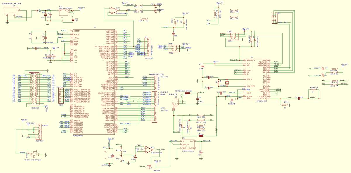
The 5f2 schematic refers to the electronic circuit diagram used in the construction of an amplifier commonly known as the “Fender Tweed Princeton.” This amplifier, introduced by Fender in the 1950s, became popular for its warm tones and simplicity. To understand the 5f2 schematic, it is important to familiarize oneself with its key components and their functions.
One of the main components in the 5f2 schematic is the vacuum tubes. This amplifier typically uses two vacuum tubes: one for preamplification and the other for power amplification. The preamp tube, usually a 12AY7 or 12AX7, boosts the incoming signal from the guitar and adds gain. The power amp tube, often a 6V6 or 6L6, drives the speaker and produces the final amplified sound. These tubes are crucial in shaping the overall tone and characteristics of the amplifier.
Another important component is the output transformer. The output transformer plays a critical role in converting the high voltage and low current signals from the power tubes into low voltage and high current signals suitable for driving the speaker. It also helps to match the impedance between the amplifier and speaker for optimal power transfer.
The 5f2 schematic also includes various resistors and capacitors. These components are strategically placed in the circuit to control the flow of electricity and shape the amplifier’s frequency response. Resistors determine the amount of current flowing through different parts of the circuit, while capacitors store and release electrical energy to shape the amplifier’s tone. These components can be modified or replaced to customize the amplifier’s sound to the player’s preference.
Additionally, the 5f2 schematic includes input and output jacks, potentiometers (volume and tone controls), and a power supply circuit. The input and output jacks allow for the connection of guitar and speaker cables, respectively. The potentiometers adjust the volume and tone of the amplifier, allowing for fine-tuning of the sound. The power supply circuit provides the necessary voltages for the amplifier’s operation.
In conclusion, understanding the 5f2 schematic is essential for anyone interested in building or modifying a Fender Tweed Princeton amplifier. By familiarizing oneself with the various components and their functions, one can gain a better understanding of how the amplifier works and how to customize its sound to suit individual preferences.
Exploring the History and Origins of the 5f2 Schematic
The 5f2 schematic is a classic amplifier design that has a rich history and is beloved by musicians and audiophiles alike. It is often associated with the iconic Fender Deluxe model, which was first introduced in the 1950s.
The 5f2 schematic, also known as the “Deluxe” circuit, was developed by Leo Fender and his team at Fender Musical Instruments Corporation (FMIC). It was one of the earliest amplifier designs that utilized a cathode bias, which allowed for a more responsive and dynamic tone.
The 5f2 schematic features a simple yet effective circuit layout, consisting of a single-ended, Class A power amp, a 12AX7 preamp tube, and a 6V6 power tube. This combination of tubes, along with its unique circuit design, gives the amplifier its distinctive character and sound.
One of the key features of the 5f2 schematic is its use of a fixed-bias design, which provides greater stability and control over the power tube’s operation. This allows for cleaner headroom and improved power tube distortion when pushed to higher volumes.
Over the years, the 5f2 schematic has undergone various modifications and improvements by both Fender and amp enthusiasts. These modifications include changes to the tone stack, input and output impedance, and the addition of various effects loops and modifications to the power supply.
Today, the 5f2 schematic remains popular among guitar players and enthusiasts who appreciate its warm, responsive tone and its ability to deliver harmonically rich overdrive at relatively low volume levels. It has become a staple in the world of boutique amplifier builders, who often use the 5f2 schematic as a starting point for their own designs.
In conclusion, the 5f2 schematic has a long-standing history and has left a significant impact on the world of guitar amplification. Its simple yet effective design, coupled with its unique tone and versatility, has made it a favorite amongst musicians and collectors for decades.
Benefits and Advantages of the 5f2 Schematic
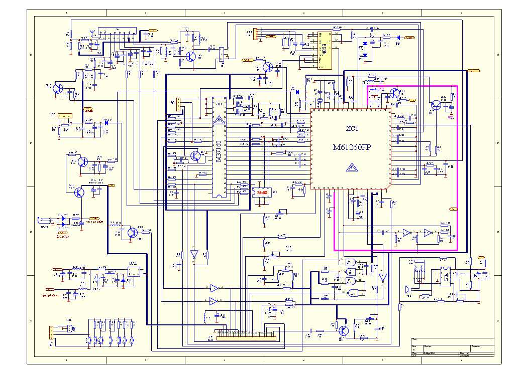
The 5f2 schematic is a popular circuit design used in guitar amplifiers. It has gained popularity among guitar players and enthusiasts due to its numerous benefits and advantages. Here are some of the key advantages of the 5f2 schematic:
1. Simplicity and Clarity: The 5f2 schematic is known for its simplicity and clarity in design. It consists of only a few components, making it easy to understand and modify. This makes it an ideal choice for beginners who are learning about amplifier circuits or for those who prefer a straightforward approach.
2. Vintage Tube Tone: The 5f2 schematic is based on vintage tube amplifier designs, which are known for their rich and warm tone. This schematic allows for the use of vacuum tubes that produce a classic sound that many guitarists prefer. It provides a vintage tone that is highly desirable in genres like blues, rock, and jazz.
3. Dynamic Response: One of the advantages of the 5f2 schematic is its dynamic response. The circuit design allows for a responsive and touch-sensitive feel when playing the guitar. It responds well to nuances in playing and provides a dynamic range that adds depth and expressiveness to the sound.
4. Versatility: Despite its simplicity, the 5f2 schematic offers a good range of tonal options. It can produce both clean tones and overdriven/distorted tones depending on the settings and components used. This versatility makes it suitable for a variety of musical styles and playing preferences.
5. Easy Maintenance and Modifications: The 5f2 schematic is relatively easy to maintain and modify. Its simple design and fewer components make troubleshooting and repairs more straightforward. Additionally, guitarists can experiment with different tubes and components to customize and fine-tune the amplifier’s sound to their liking.
The 5f2 schematic has become a popular choice among guitarists and amplifier enthusiasts due to its simplicity, vintage tone, dynamic response, versatility, and ease of maintenance and modifications. Whether you are a beginner or an experienced player, the 5f2 schematic can offer you a classic and highly customizable amplifier option for your guitar setup.
Common Modifications and Upgrades for the 5f2 Schematic
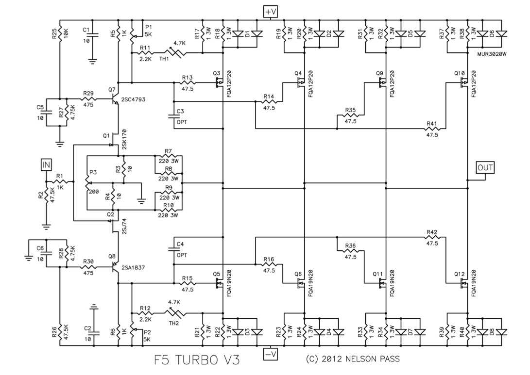
The 5f2 schematic is a popular choice among guitarists who are looking to modify and upgrade their amplifiers. This classic circuit, commonly found in Fender Champ amplifiers, provides a vintage tone and a simple design that lends itself well to customization. Here are some common modifications and upgrades that can be made to the 5f2 schematic to enhance its performance and versatility:
1. Tube Swapping
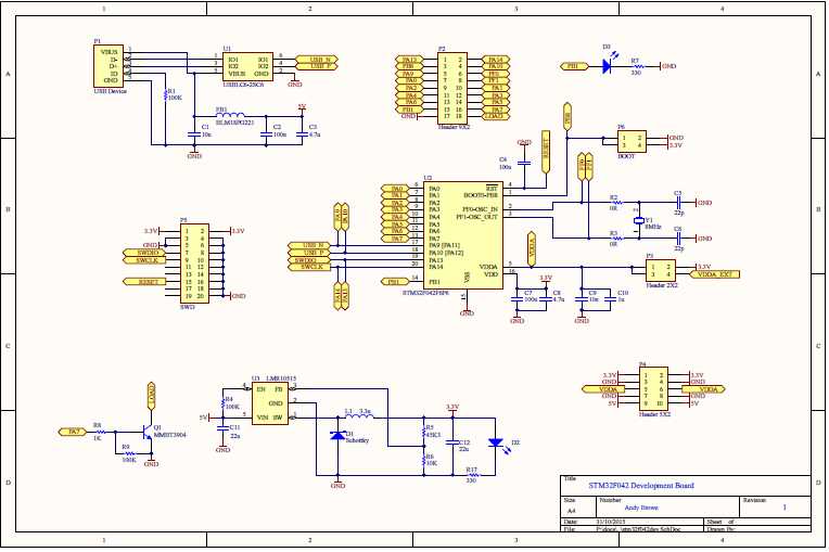
One of the easiest and most effective modifications for the 5f2 schematic is to swap the tubes. By experimenting with different types of power and preamp tubes, guitarists can achieve different tones and levels of gain. Popular choices for power tubes include the 6V6, 6L6, and EL84, while options for preamp tubes include the 12AX7, 12AT7, and 12AY7. Tube rolling can significantly change the overall sound and response of the amplifier.
2. Speaker Upgrade
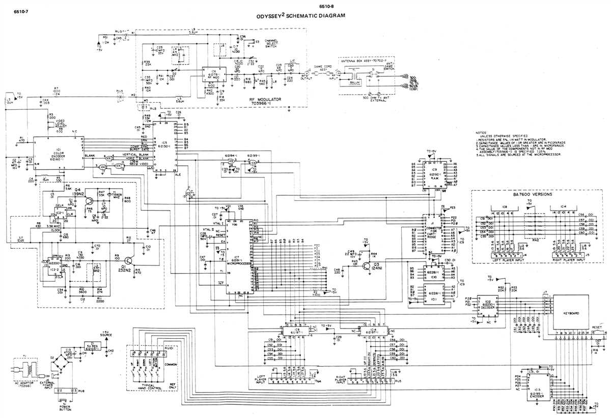
Another popular modification is to upgrade the speaker. The stock speaker in the 5f2 circuit is usually a 8-inch speaker, but many guitarists choose to replace it with a larger or higher-quality speaker to improve the overall tone and output. Options include speakers from brands like Celestion, Jensen, and Eminence, which can provide increased clarity, better bass response, or a different overall character.
3. Tone Stack Modifications
The tone stack in the 5f2 schematic can be modified to alter the frequency response and shape the tone. Some guitarists may prefer a more scooped sound, while others may want a mid-heavy tone. Adding a switch to toggle between different capacitor values or resistors can give players the ability to adjust the tone to their liking. These modifications can be done in a way that allows the amplifier to retain its original tone when the switch is in the stock position.
4. Power Scaling
Power scaling is a modification that allows guitarists to attenuate the power output of the amplifier, making it more suitable for different playing environments. By adding a power scaling circuit, players can achieve power tube saturation at lower volumes, allowing them to achieve the desired tone without excessive volume. This modification can be particularly useful for recording or practicing at home.
These are just a few examples of the many modifications and upgrades that can be made to the 5f2 schematic. Each modification can have a significant impact on the overall tone, responsiveness, and versatility of the amplifier, allowing guitarists to customize their sound to their exact specifications. Whether it’s tube swapping, speaker upgrades, tone stack modifications, or power scaling, there are plenty of options to explore when it comes to enhancing the 5f2 circuit.
Troubleshooting and Maintenance Tips for the 5f2 Schematic
In order to ensure optimal performance and longevity for your 5f2 schematic, it is important to follow some troubleshooting and maintenance tips. By addressing common issues and taking care of the amplifier, you can ensure that you get the best possible sound and avoid any unnecessary damage. Here are some tips to keep in mind:
Troubleshooting Tips
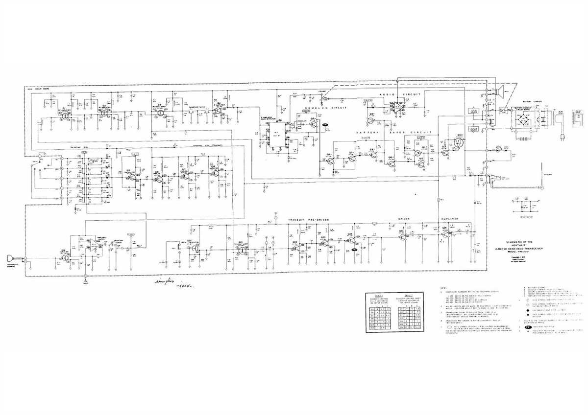
- Check for loose connections: Make sure all cables and components are securely connected to the circuit board.
- Inspect the tubes: Look for any signs of wear or damage on the tubes. If you notice any issues, such as a weak or distorted sound, it may be time to replace them.
- Test the capacitors: Capacitors can degrade over time, affecting the performance of the amplifier. Use a multimeter to check if any capacitors need to be replaced.
- Look for overheating: Excessive heat can cause components to fail. Check for any hot spots on the circuit board or around the tubes.
- Test the pots and switches: Make sure all pots and switches are working properly and not causing any crackling or noise when adjusted.
Maintenance Tips
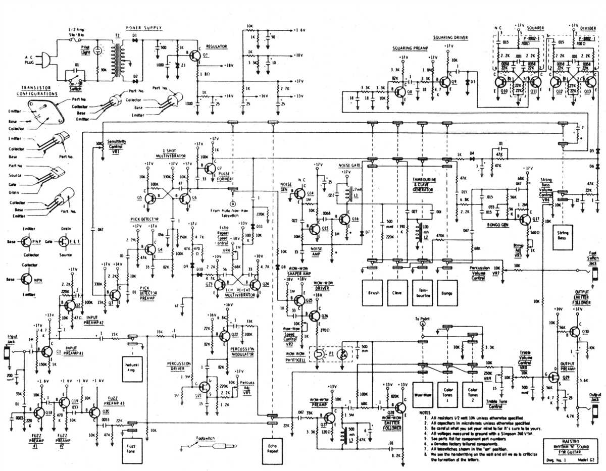
- Clean the chassis: Regularly remove dust and debris from the chassis to prevent heat buildup and improve overall performance.
- Keep the tubes in good condition: Avoid moving the amplifier while the tubes are still hot, as this can cause damage. Additionally, regularly check and clean the tube sockets to ensure proper connections.
- Use the correct power supply: Make sure you are using the correct power supply voltage for your 5f2 schematic to prevent damage to the components.
- Store in a safe environment: When not in use, store the amplifier in a cool, dry place to prevent moisture and other harmful conditions.
- Follow proper shutdown procedures: When turning off the amplifier, allow it to cool down for a few minutes before unplugging it to avoid any potential damage.
By following these troubleshooting and maintenance tips, you can ensure that your 5f2 schematic remains in optimal condition, providing you with great sound and reliability for years to come.