x 75 6ES7 AGXB0. CPU C AC/DC/RLY, 6ES7 BHXB0.
SM DC . S System Manual, English.
6ES7 . We use cookies to personalise content and ads and to analyse our traffic.
We also share information about your use with our analytics partner. Learn more. Product.
Article Number (Market Facing Number), 6ESBHXB0. Product Description, SIMATIC S, Digital input SM , 16 DI, 24 V DC, Sink/. 6ESBHXB0. SIMATIC S, DIGITAL INPUT SM , 16 DI, 24VDC,. SINK/SOURCE INPUT.
Supply voltage. Rated value (DC).
CPU C Wiring Diagrams. Table 1. CPU C AC/DC/Relay (6ES7 1BGXB0).
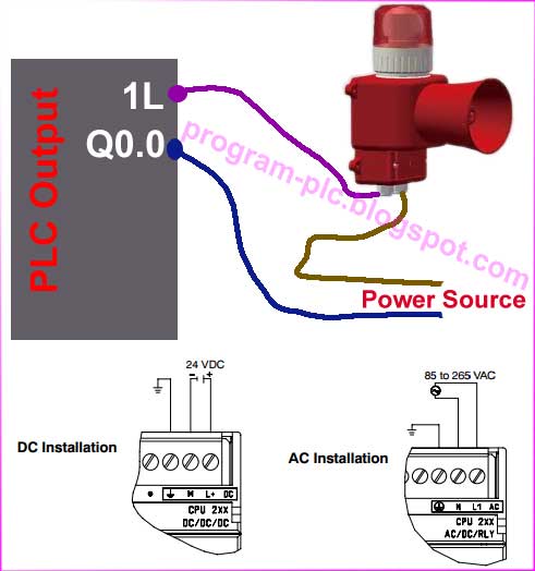
① 24 VDC Sensor Power. Out.
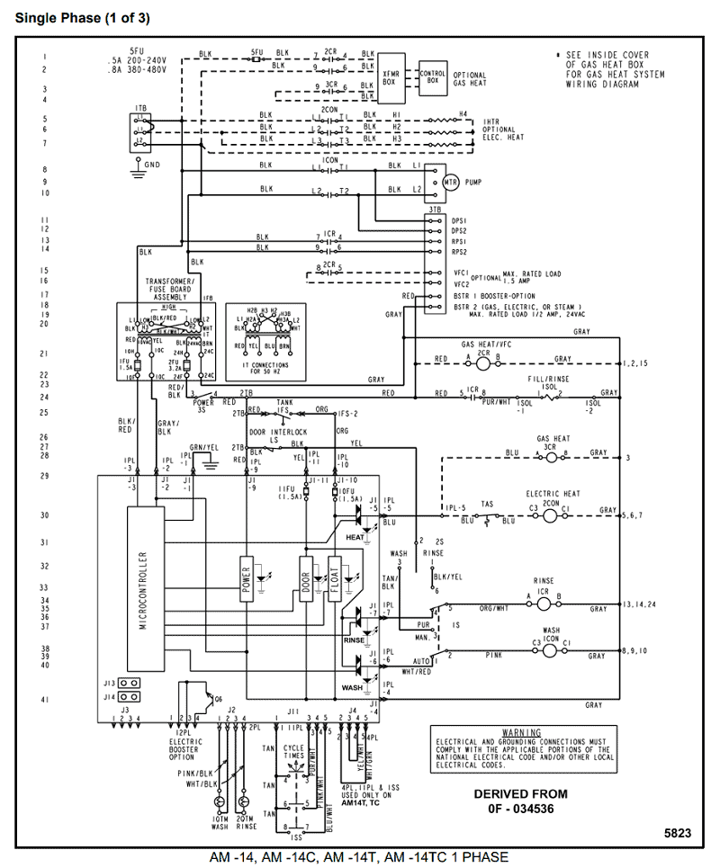
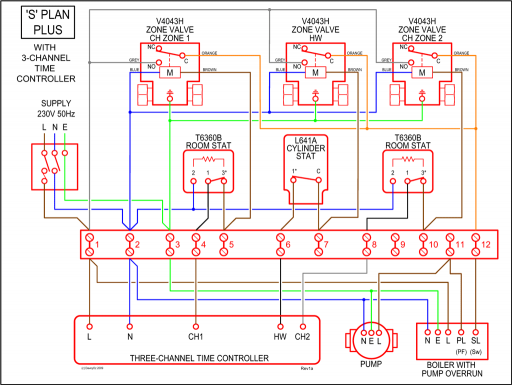
For additional.Easy Book_____ Preface Introducing the powerful and 1 _____ flexible S SI. Wiring Diagrams Type S AC Combination Magnetic Starters Class and The diagram symbols in Table 1 are used by Square D and, where applicable, conform to NEMA (National Electrical Manufacturers A ssociation) WIRING DIAGRAM. M A1 A2 M.
FAQ What are the differences between the digital SIMATIC input modules of S/S and ET SP with regard to standard IEC ?. The digital input modules of the SIMATIC S/S and the ET SP meet the requirements of the IEC standard. This is the only standard valid worldwide for programmable logic controllers.
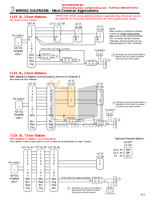
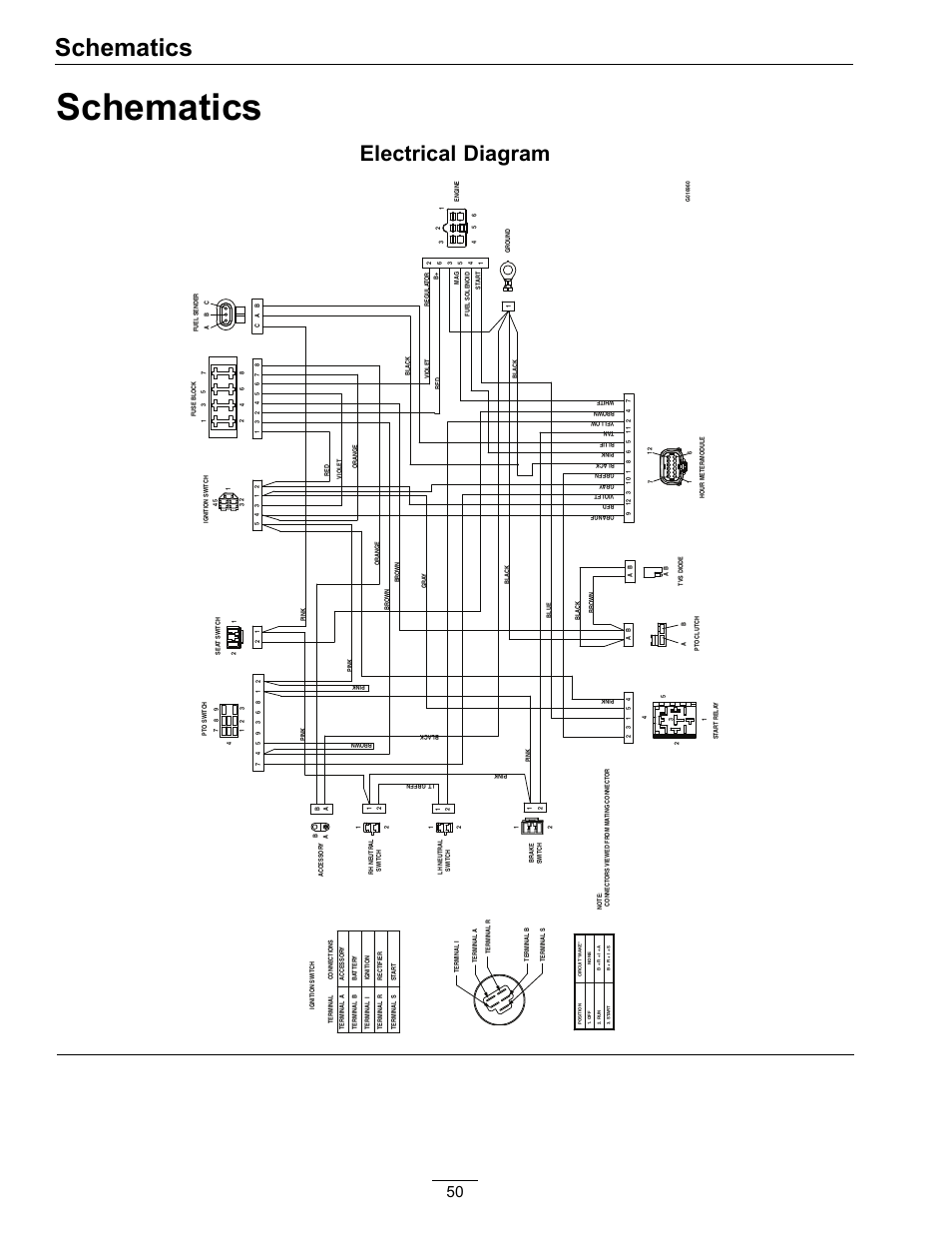
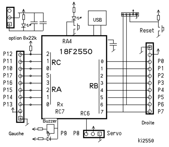
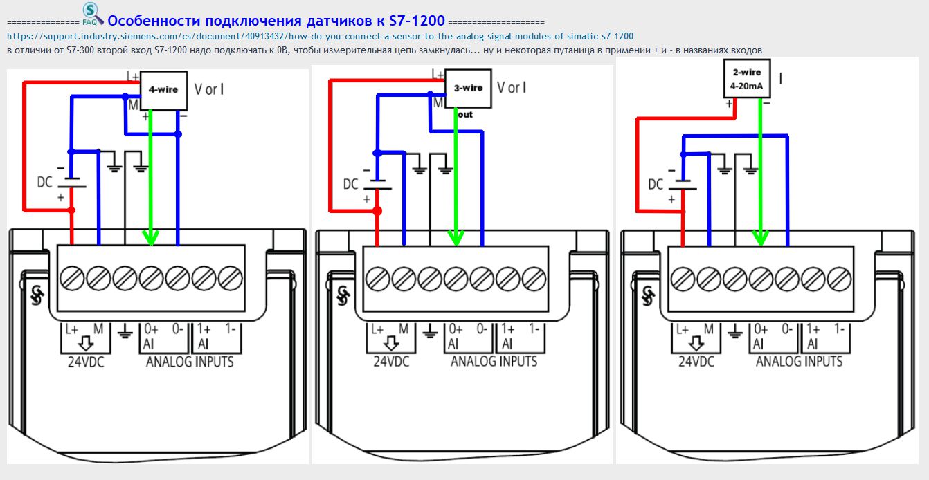
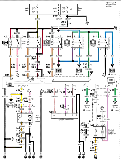
Best Of Generac Generator Wiring Diagram – Allowed to be able to my blog, in this particular time period We’ll provide you with about generac generator wiring diagramNow, this is actually the first picture: Cute Predator Generator Wiring Diagram Gallery Electrical from generac generator wiring diagram, source:schematron.org When you connect a thermocouple to the SM Thermocouple signal module, the two dissimilar metal wires are attached to the module at the module signal connector. The place where the two dissimilar wires are attached to each other forms the sensor thermocouple.6ESBHXB0 / 6ESBHXB0 – Siemens SM – 16 x 24VDC Input (Sink or Source)WIRING DIAGRAMS
