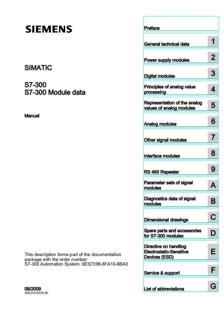
This manual contains notices you have to observe in order to ensure your personal Analog input module SM ; AI 8 x 16 bit; (6ESNFAB0) . Manufacturer Material ID, 6ESNFAB0.
Net Weight (kg), Product Dimensions (W x L x H), Not Available. Minimum Order Quantity, 1. Analog input module SM ; AI 8 x 16 bit; (6ESNFAB0) .. ..

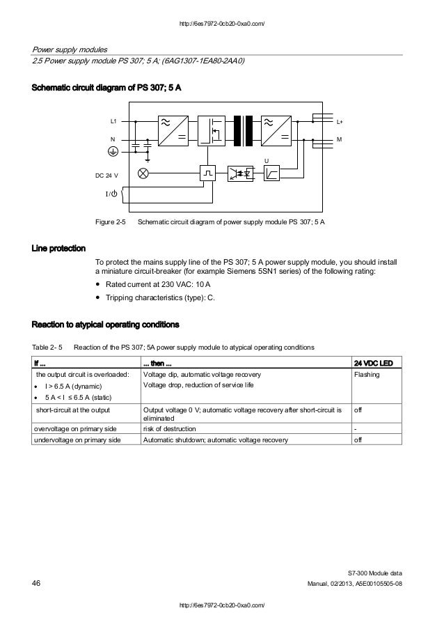
be used as load power supply. Wiring diagram of PS ; 2 A.
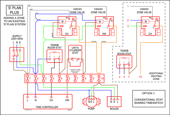
Need Supply Connection Diagram for AI 63SNFAB0 LIVE PLC for the Analog Module 6ESNFAB0, i have already searched for its Hi, download the S Module Data User Manual from this link. Analog input module SM ; AI 8 x 16 Bit; (6ESNFAB0). Wiring diagram of PS ; 2 A Block diagram of power supply module PS ; 2 A.Abstract: 6ES7 KFAB0 KBAB0 Wiring Diagram 6es7 analog module 6ESKFAB0 KFAB0 6ESKBAB0 6es7 HBAB0 Wiring Diagram pt siemens HBAB0 Text.
wiring and commissioning of the SIMATIC S and ET MP systems. The STEP 7 online help supports you in the configuration and programming.
Device information Product manuals contain a compact description of the modulespecific information, such as – properties, wiring diagrams, characteristics and technical specifications. Moreover, the pin assignment in the wiring is unchanged.

This means that circuit and wiring diagrams can be universally used. For all analog input modules the components for shielding like power supply element, shield bracket, and shield terminal are included in the scope of delivery 6ESNFAB0.
SM AI 8xU/R/RTD/TC HF High. Abstract: 6ES7 KFAB0 KBAB0 Wiring Diagram 6es7 analog module 6ESKFAB0 KFAB0 6ESKBAB0 6es7 HBAB0 Wiring Diagram pt siemens HBAB0 Text.
There are no slot rules: The input addresses are defined by the slots. Wiring Analog output module AQ 4xU/I ST (6ESHDAB0) Manual, 01/, A5E 13 Block diagram and terminal assignment for the voltage output The following figure shows an example of the wiring options: 2-wire connection, without compensation for line resistances.
4-wire connection, with compensation for line resistances.6ESKFAB0 AI Wiring – Entries – Forum – Industry Support – Siemenswiring manual for 8 AI(6ES7 7NFAB0) – Entries – Forum – Industry Support – Siemens