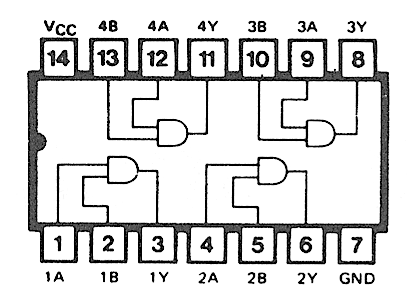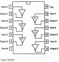
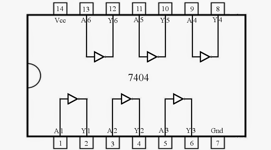
74LS04 IC. Component details of NOT Gate IC including pin diagram, description & 74LS04 NOT Gate IC datasheet.
IC PIN CONFIGURATION OF 74LS04 datasheet, cross reference, circuit and application notes in pdf format. 74LS04 hex Inverter.
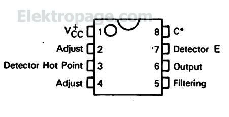
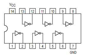
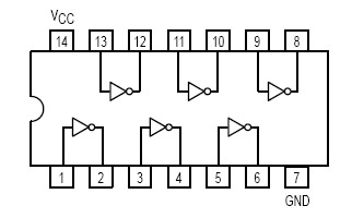
This device contains six independent gates each of which performs the logic INVERT function. Pin Arrangement. Short Circuit Current (Note 1).
– – mA. VCC = MAX. ICC.
Power Supply Current. Total, Output HIGH.
mA. VCC = MAX.
ICC p. Total, Output LOW.
74LS SOP − NS. Tape and reel.
SN74S04NSR. 74S SSOP − DB.
Tape and logic diagram (positive logic). 1A .
Digital Electronics: Logic Gates – Integrated Circuits Part 1
Not more than one output should be shorted at a time, and the duration of the short-circuit should not exceed one second.Pin Diagrams. See more What others are saying “Full Subtractor Circuit and Its Construction” “Pin diagram for 74LSN and 74LS04” from schematron.org Circuit Diagram Arduino Coding Chips Computers Circuits Fries French Fries Programming “Pin Diagram of IC MC74HC73A” from schematron.org Pic Microcontroller Diagram Projects To Try. Six Hex Inverters in a Pin DIP Package.
Outputs Directly Interface to CMOS, NMOS and TTL. Large Operating Voltage Range. Wide Operating Conditions.
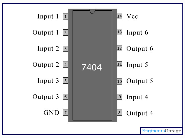
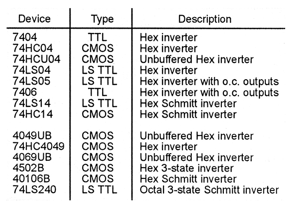
Not Recommended for New Designs Use 74LS04 . Abstract: 74LS04 pin configuration pin configuration 74LS04 74LS04 74LS04 NOT gate AD 74LS04 function table 74HC04 74ls04 pin diagram welwyn f6 Text: to the EVALCONTROL BOARD or other system.
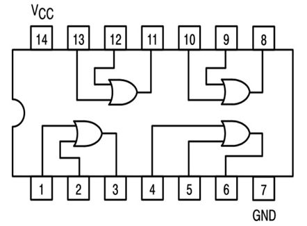
The pinout for the J1 connector is shown in Figure 2 and. Original: PDF. Watch video · Pin diagram of 74LS04 IC is shown below. Components Power supply (5v), 1K resistor (2 pieces), Ω resistor, 74LS86 QUAD EX-OR GATE IC, 74LS04 HEX NOT gate chip,1 LEDS, buttons (2 pieces), nF capacitor (2 pieces) Connecting wires, breadboard.
74LS04 IC. Component details of NOT Gate IC including pin diagram, description & 74LS04 NOT Gate IC datasheet. is a NOT gate IC.
Tutorial for 74LS08,74LS04,74LS32 (Anot OR Bnot) And (A or B) Taglish
It consists of six inverters which perform logical invert action. The output of an inverter is the complement of its input logic state, i.e., when input is high its output is low and vice versa.74LS04 NOT Gate IC | IC Datasheet74LS47 IC | 74LS47 Datasheet | Pin Diagram & Description
