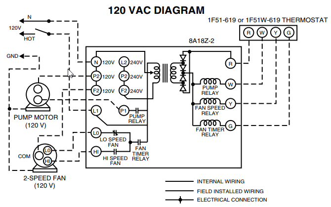
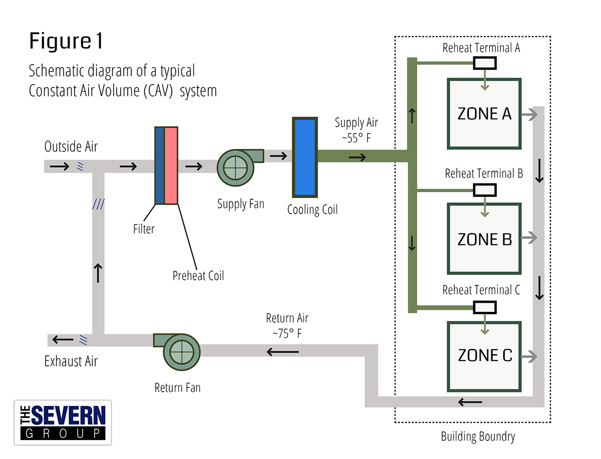
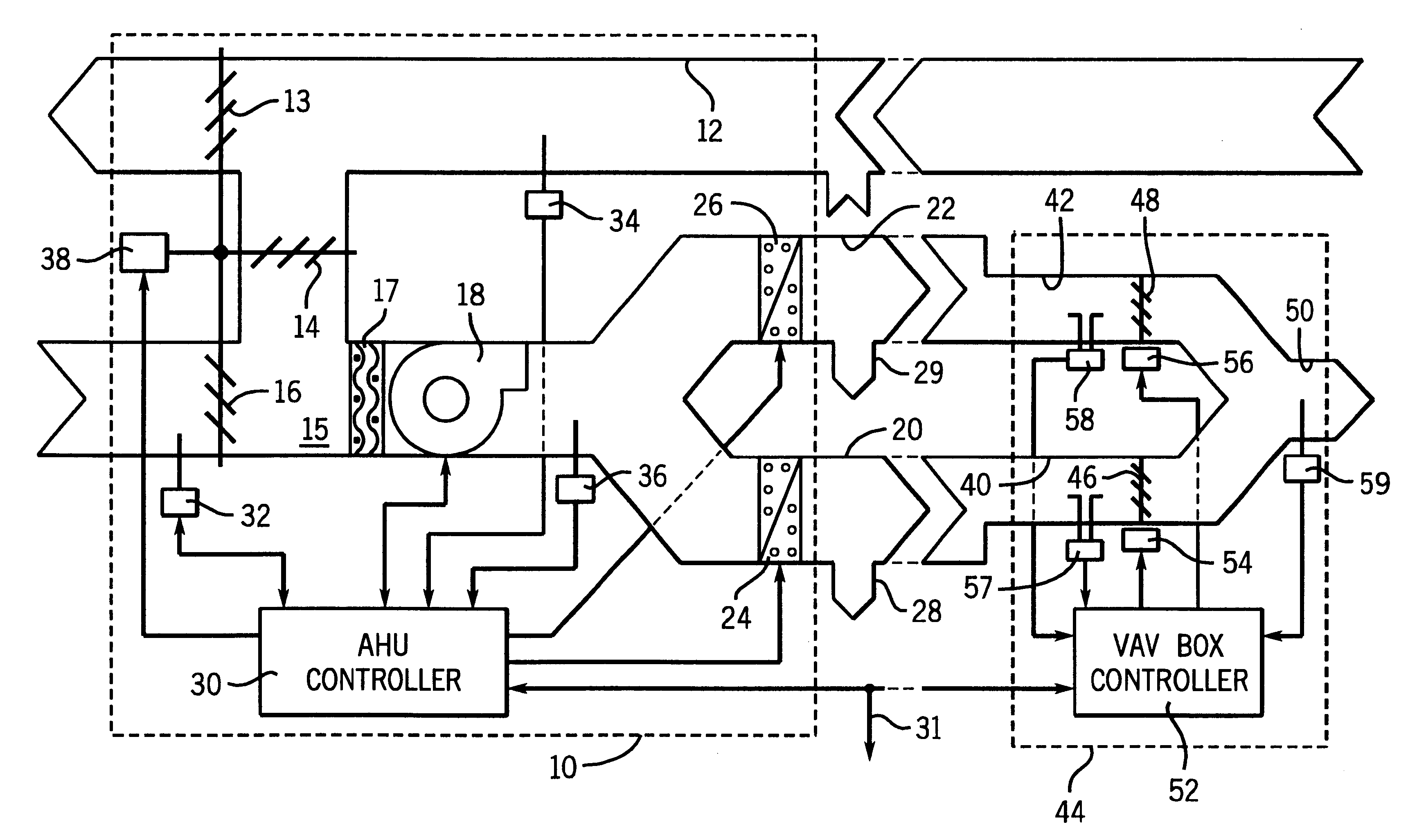
Air is blown over coils at the air handler in parallel.
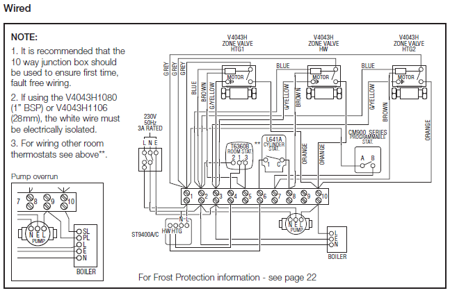
• Each zone Use electronic VSD at the fan motor; supply and return fans should track together. Example of Schematic for Alerton Controls. Actuator Fan Powered VAV Terminal Unit.
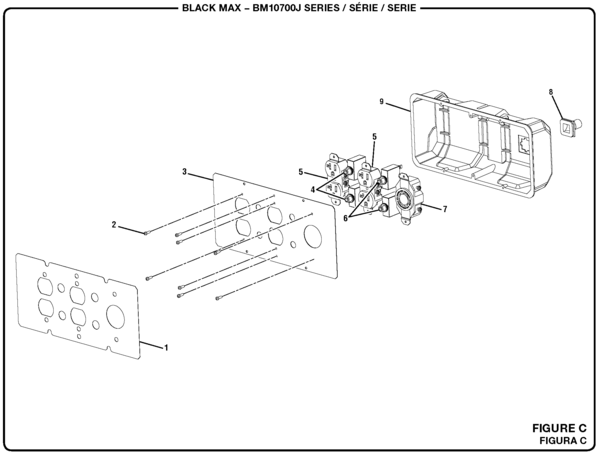
*MSH-BT ALERTON BACtalk Microset II WALL UNIT Push-buttons also support fan-speed control, and the LCD shows current fan-speed. . Immersion Sensor w/ Galvanized Junction Box ..
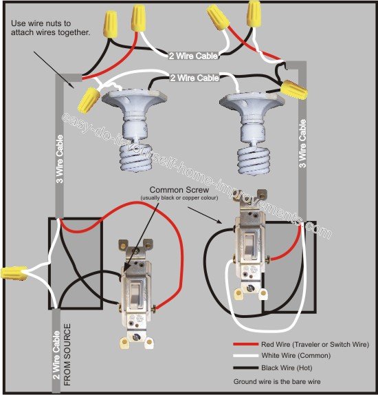
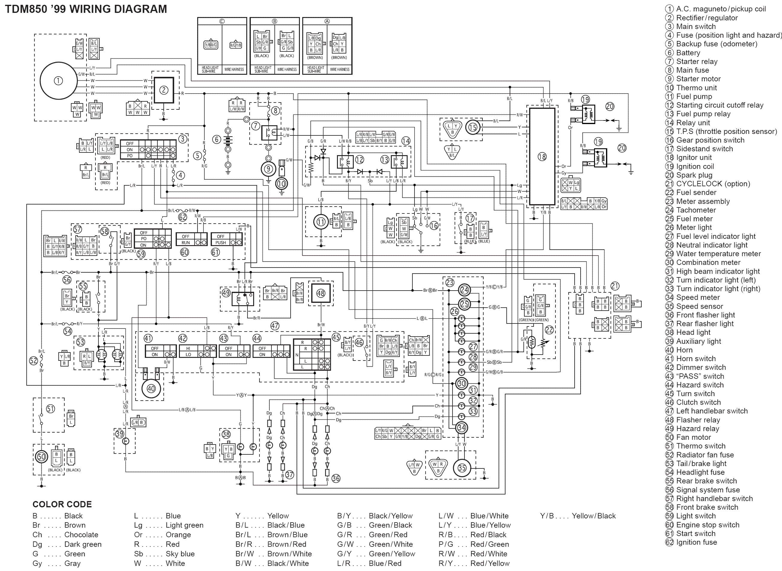
Wiring Diagrams easy parallel connection in the power system. the small footprint of the ESDk provides greater. Alerton’s Building Suite allows Envision for BACtalk to act as a virtual computing configuration, and field checkout tool set designed specifically for installation and .
See “Network scenario diagrams” in the Alerton Building Suite Getting . Power No independent power supply required.
. air temperatures, and fan status.
appropriate intervals throughout this manual. Warnings are provided to alert installing ..
Factory Installed Alerton VAVS w. LMBT.

TU16 . Figure 4. Parallel fan-powered terminal unit (L) & series fan-powered terminal units (R) .
Low-height terminal units have a removable bottom panel. Clearances. Alerton Dealer .
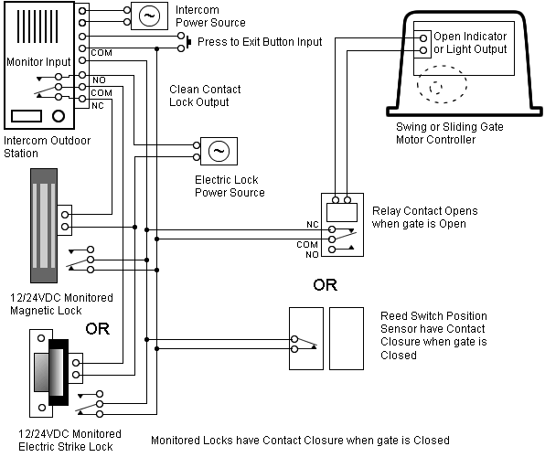
System configuration diagrams in simplified block format. 2.
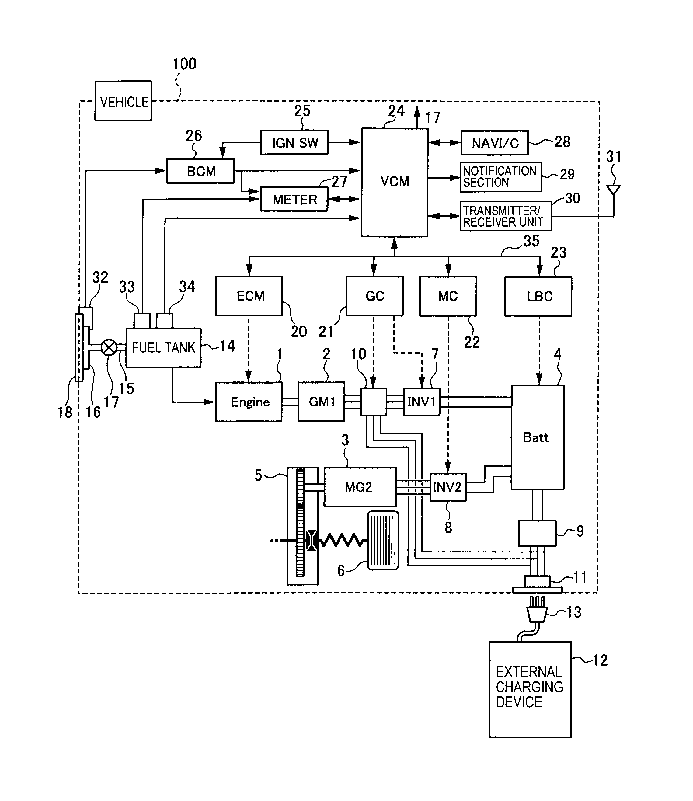
Electrical drawings that show all system internal and external connection points, For applications using variable speed parallel fans, provide a single analog.Various AHU Fan Systems requirements. •Multi-Zone and Dual Duct Systems • Reset hot and cold deck temppps based on zone loads & temperatures.
Smart Controls
•Variable Air Volume (VAV) • Use electronic VSD at the fan motor; supply and return fans should track together. Use PI or PID to create fan schematron.org together.
Use PI or PID to create fan. The Alerton® BACtalk® VAV-SD2A is a versatile, BACnet-compliant field controller that provides pressure-independent control of any single-duct variable air volume (VAV) box. It is particularly suited for controlling VAV series fan boxes equipped with a variable speed fan. Electric Heat Wiring Trane Vav Box – Block And Schematic Diagrams • trane vav wiring diagram wiring diagram and schematics Trane Varitrac Dampers Trane VAV Box Cone.
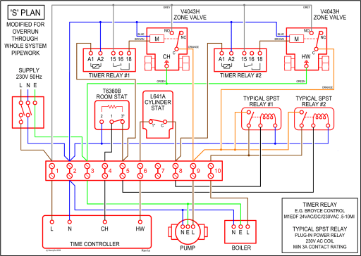
Wiring Vav Box – The Automated Logic® ZASF secondary VAV damper is an integral component of the WebCTRL® building automation system. The ZASF is intended specifically for VAV.
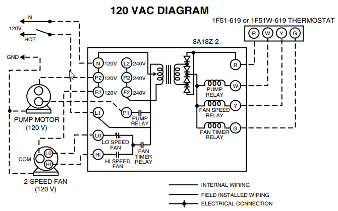
additional fan(s). To fan.
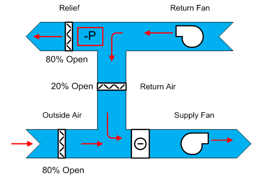
5 To Junction Box To Fan Wiring Canopy Module (CM-FQ1): Use wire connectors to join wires as indicated below and in the wiring schematron.org any unused wires. Wire Fan Neutral Black White Disconnect Fan Wires † Remove the Fan Canopy Enclosure from the ceiling fan mounting bracket.

So onto the 2nd case, if the motors are in parallel then when the controller is giving full power each motor will see the full 24V, now as Power = V 2 /R and we haven’t changed R this will cause each motor to give 4 x the power i.e. W. Whilst this is an excellent way to get more performance it probably won’t do too much for the reliability.Smart Controls | WBDG – Whole Building Design GuideField Controller
