TPS Wire. TPS. MAF Wire.
MAF. Year. Model.
Engine. Color.
Location. Color Model.
Engine. Color. Location.
Color. Location Footnotes.
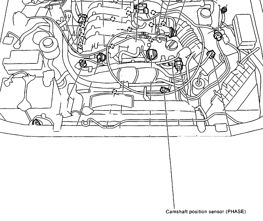
GTI Indicates that you will be connecting to the (MAF) Mass air flow sensor, all others . The MAP (manifold absolute pressure) Sensor plug is no exception. This kit is also great if you need to extend your MAP sensor wire harness to accommodate .
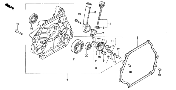
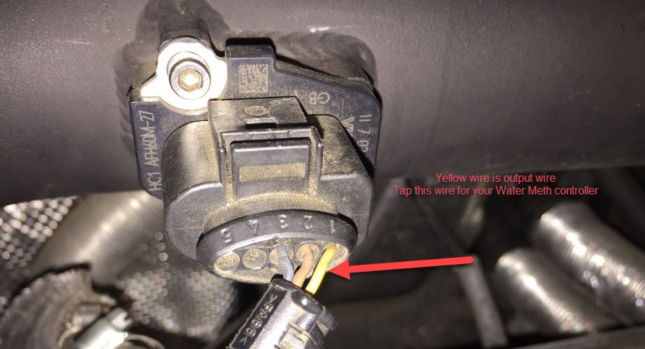
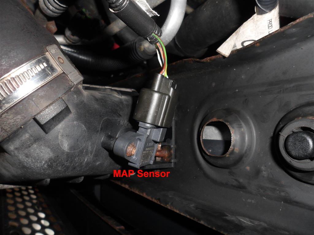
Thread: Help with map sensor wiring a hack job was here >:( so wiring diagram says pin 1 on plug should b brown with a black tracer, pin 3. In this series of servicing all the sensors that may hurt your Eos T driving This sensor also exists in other VW that uses T engine such as Golf GTI, CC. I really need a pic or diagram of the connector for the MAP Sensor or some call it Car I have is a stock GTI MKV.
What are you trying to do with the wiring, you can’t just install a bigger map sensor and have it work.WIRING DIAGRAM BY MODEL This document describes car models to which the AFC neo (Product code: A) is applicable, and ECU terminal arrangement drawings. For the operating method and precautions for the AFC neo, refer to the Instruction Manual. When installing the AFC neo, both this document and the Instruction Manual are required.
Jul 26, · Peugeot GTi-6 MAP sensor testing. Published on Jul 26, Peugeot GTi-6 MAP sensor testing.
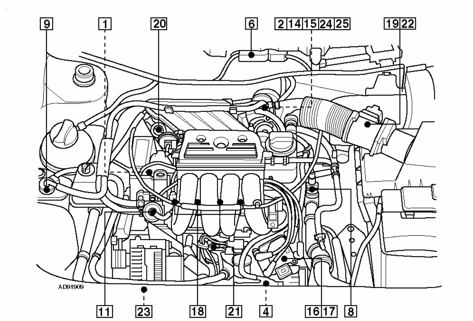
Category MAP Sensor & Wiring Diagram – Duration: PEUGEOT ALL MODELS WIRING DIAGRAMS – GENERAL CONTENTS. OPERATING INSTRUCTIONS DOCUMENT: LIST OF COMPONENTS (SECTION 1): Schematic diagram. Wiring diagram.

Installation diagram. 2 – CONSTITUTION OF THE DIAGRAMS: Schematic diagram: map reading lamp. selector lever lamp. ignition switch lamp.
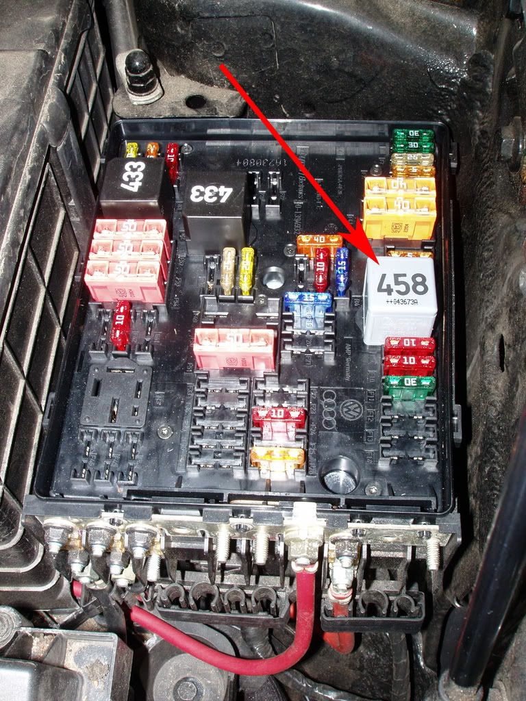
68 Vw Bug Fuse Diagram – Reveolution Of Wiring Diagram • thesamba com beetle late model super up view VW Beetle Fuse Box Diagram VW GTI Fuse Diagram. Vw Gti Fuse Box Map – Here is a terrific image for fuse box diagram vw gti turbo.

We have been looking for this image through internet and it originated from reliable. Wiring diagrams 12•31 Engine electrical systems – cc non-catalyst (D6E/XU9JA K) (with its circuit diagram) Part framing (without its circuit diagram) Part extract Part extract Indicator Thermocouple Electrodes Oxygen sensor Supply socket NPN transistor PNP transistor Connection indicating line No extremity. Wiring diagrams 12•Need help with Boost Sensor MK5 GTI | VOLKSWAGEN GTI Forumschematron.org – Looking for pic or diagram of MAP Sensor for GTI MK5
