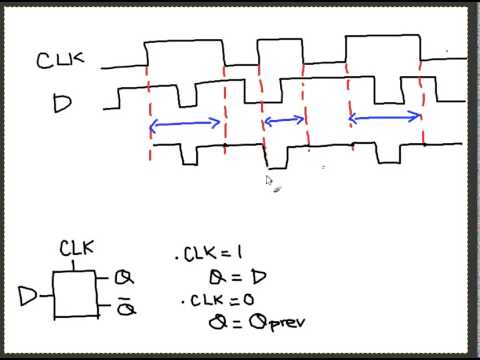
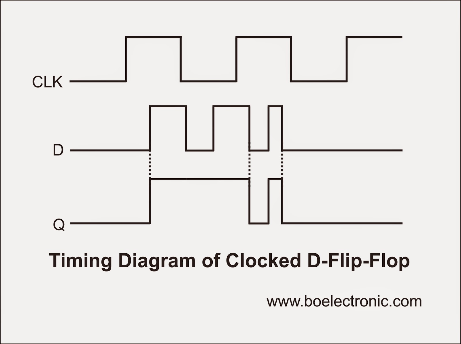
G is indeed a voltage that was at a higher level and then drops to a lower level. This is dependent on the logic level of the D-latch, for example if.
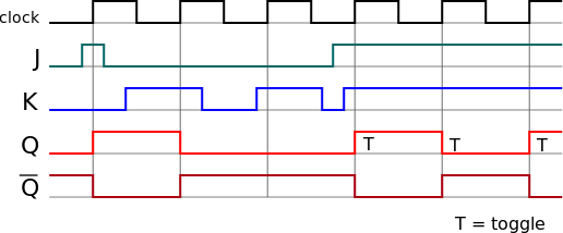
Figure Master-slave D flip-flop. D Q.
Q. Master.
Slave. D.
Clock. Q.
Q. D Q. Q.
Q m. Q s.
D. Clock. Q m.
Q Q s. = D Q.
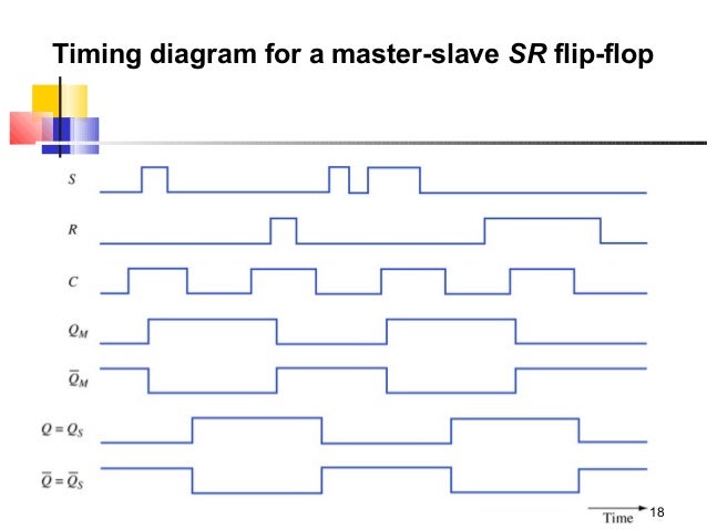
Q. (a) Circuit. (b) Timing diagram.

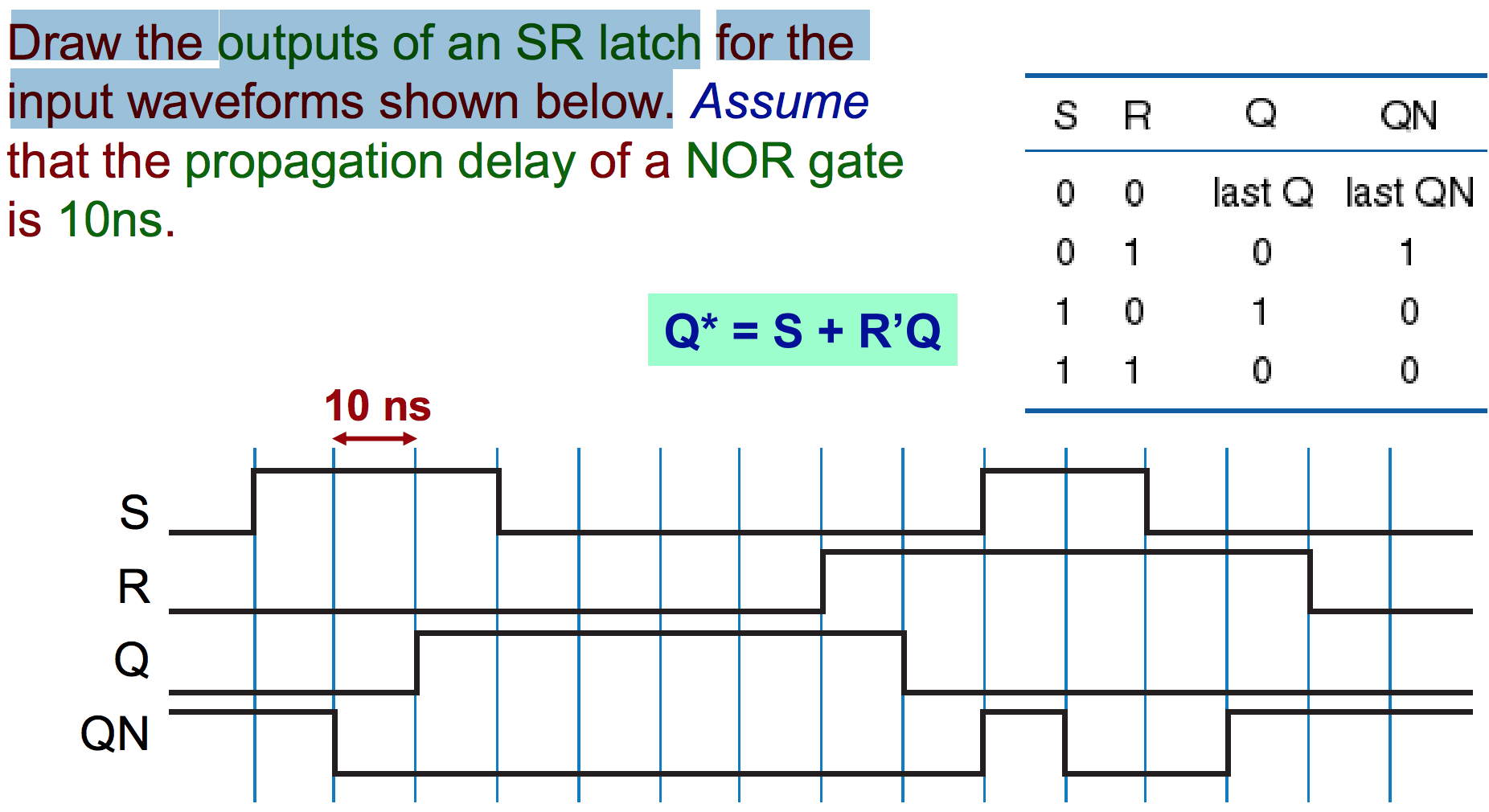
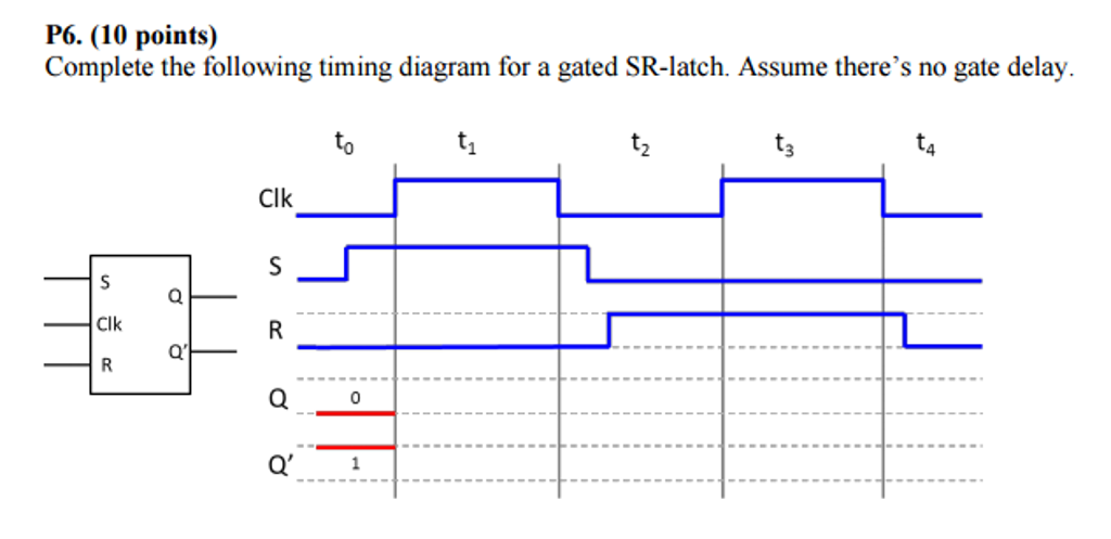
Timing diagrams. □ T flip-flops and SR latches. 2.
CSE, Lecture The D latch. ◇ Output depends on clock.

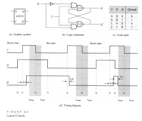
□ Clock high: Input passes to output. □ Clock . Flip-flops, D-type flip-flops explained, Data latch, ripple-though, edge-triggering, synchronous and Timing Diagram for a Level Triggered D Type Flip-flop.
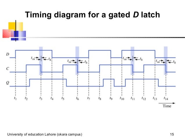
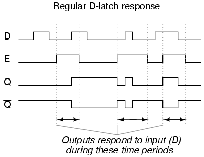
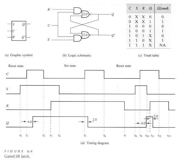
G is indeed a voltage that was at a higher level and then drops to a lower level. This is dependent on the logic level of the D-latch, for example if.The D latch is nothing more than a gated S-R latch with an inverter added to make R the complement (inverse) of S.
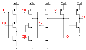
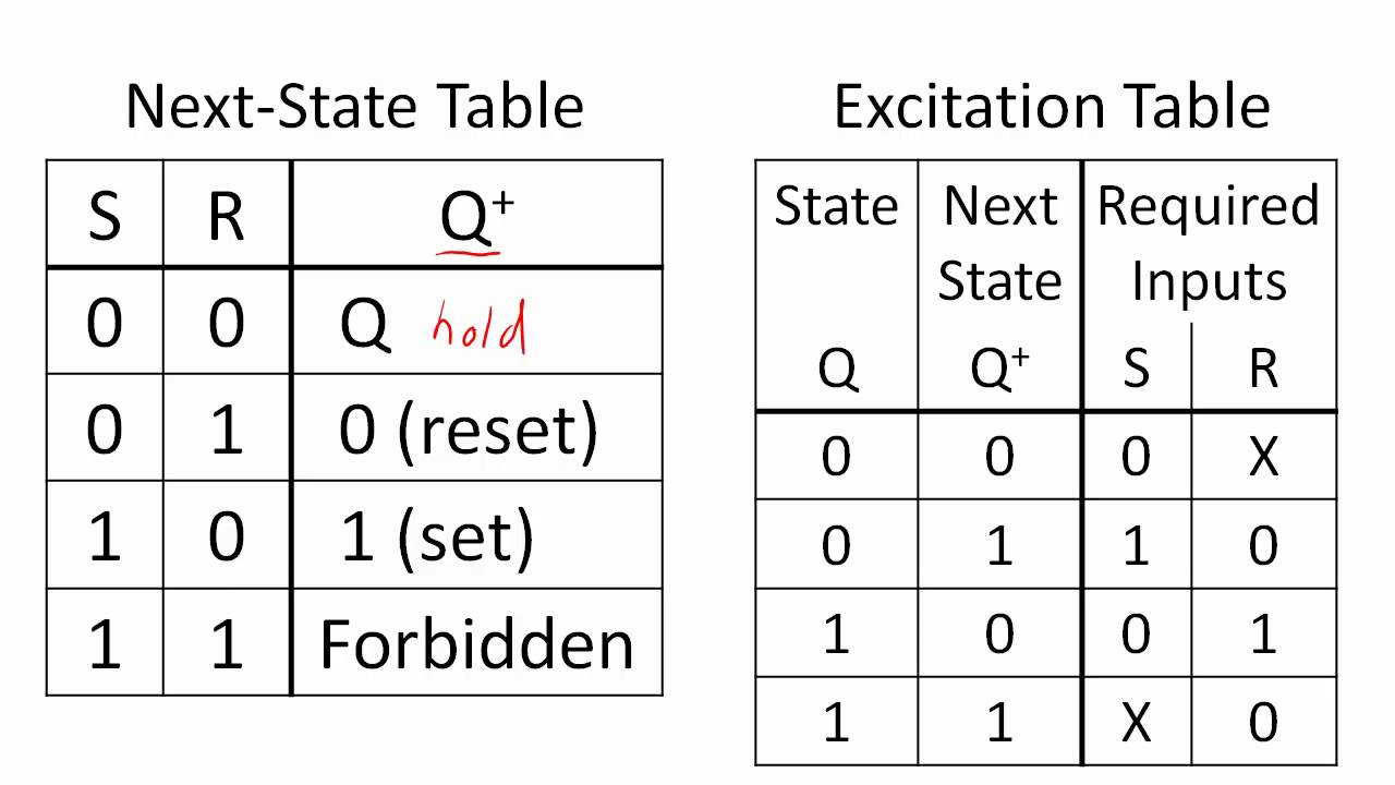
Let’s explore the ladder logic equivalent of a D latch, modified from the basic ladder diagram of an S-R latch: An application for the D latch is a 1-bit memory circuit. Chapter 7 – Latches and Flip-Flops Page 4 of 18 From the above analysis, we obtain the truth table in Figure 4(b) for the NAND implementation of the SR latch. Q is the current state or the current content of the latch and Q next is the value to be updated in the next state.
D Q ff Q latch Latches versus flip-flops D Q Q CLK D Q Q CLK CSE, Lecture 14 10 The master-slave D D Q CLK Input Master D latch D Q Output Slave D latch master-slave D flip-flop Class example: Draw the timing diagram. The Gated D Latch Timing Diagram.
February 6, ECE A – Digital Design Principles 28 The Edge Triggered D Flip-Flop The D Flip-Flop (cont) State Diagram 1 0 D = 0 D = 1 D = 1 D = 0. February 6, ECE A – Digital Design Principles 32 The Master-Slave D Flip-Flop.
The advantage of the D flip-flop over the D-type “transparent latch” is that the signal on the D input pin is captured the moment the flip-flop is clocked, and subsequent changes on the D input will be ignored until the next clock event.D Type Flip-flopsFlip-flop (electronics) – Wikipedia