Do not see that in the electrical diagram.
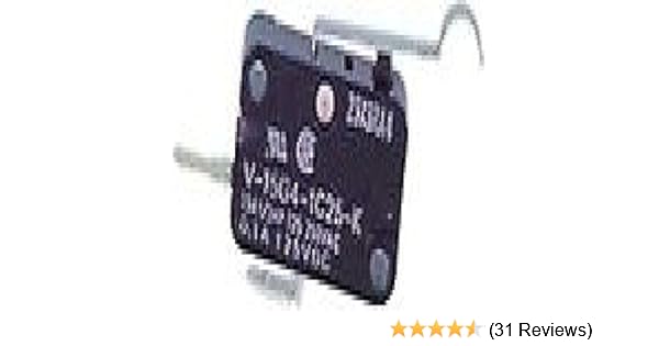
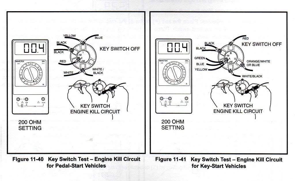
Technician: When I unplug the wires from the top micro switch it does not start so that must be the starter micro switch. I then if you get spark when pedal is released, Igniter and coil are good!

Makes. When throttle pedal is depressed I get no spark but when released it gives spark. The micro switches and coil is OK and I wonder if it could be the.
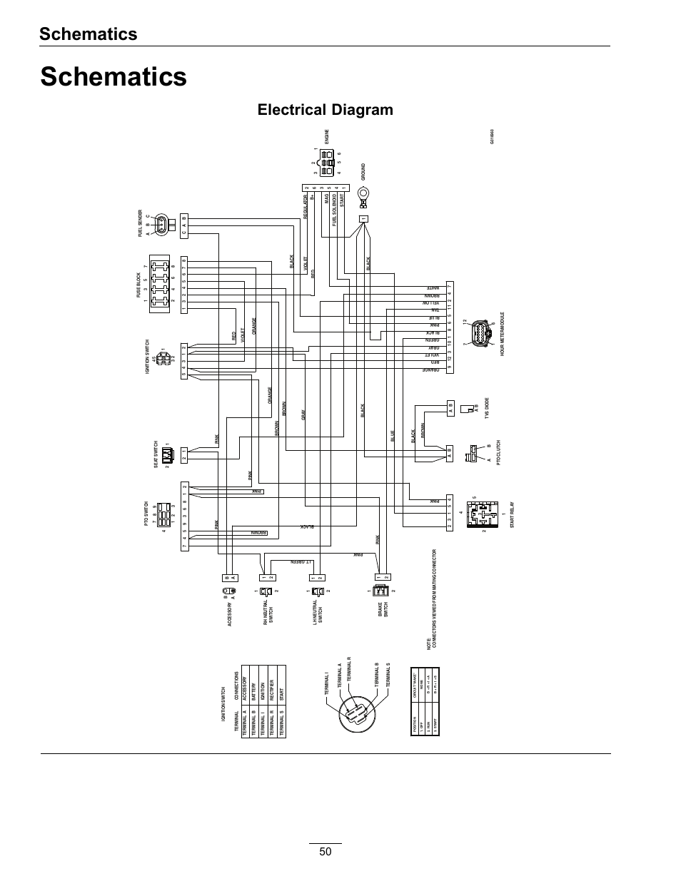
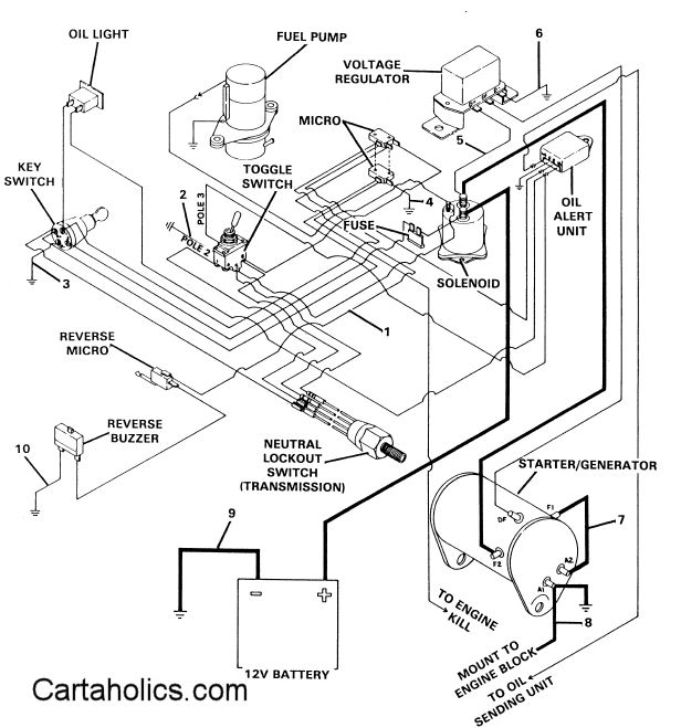
Here’s the main wiring diagram for your cart: should see the plug sparking and hear it clicking while the gas pedal is depressed (and the motor tries to start). If you do not have the appropriate maintenance and service manual, you may order one . Engine Ignition Circuit.
. Accelerator Pedal Limit Switch. The neutral lockout circuit prevents the operator from starting the vehicle in NEUTRAL .

I think it is a electrical problem. There are micro switches on the gas pedal that could be bad, there should . I think you may have a kawasaki engine fe My gas club car won’t start the battery is fully charged but the.
ELECTRICAL COMPONENT BOX, GASOLINE VEHICLE—CARRYALL II PLUS AND VI. . CARBURETOR ASSEMBLY, FE ENGINE—CARRYALL I AND II.
. PEDAL LIMIT SWITCH, READ THE POTENTIOMETER SET VOLTAGE FROM THE DO NOT start vehicle until all occupants (two (2) per seat maximum) are .Apr 27, · Looks like there’s a limit switch that opens the start circuit when the gas pedal is pushed. A solenoid.
(nothing in neutral but is it supposed to start in neutral?) I loosened up the starter belt tension and the starter now spins when the pedal is depressed. Engine may be locked up?
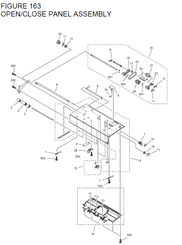
Cant say without a wiring diagram. lugnut. GENERAL WIRING DIAGRAM. Next.
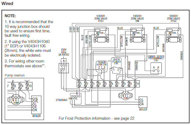
TECHNICAL ASSISTANCE. Solenoid Does Not Close.
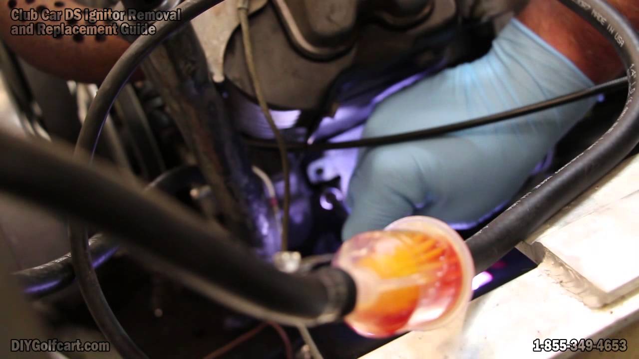
accelerator start switch. Back.
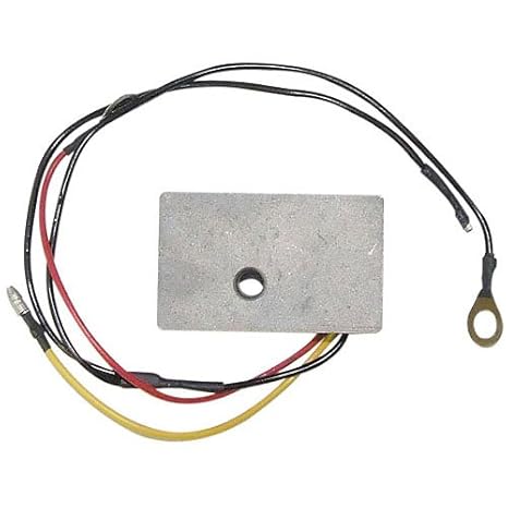
The solenoid is closed by the following steps. Next. First battery positive is supplied to pedal. Pin 1 does vary between.4V – V when moving the accelerator pedal.
May 11, · Club Car starter/generator brushes The starter / generator has a dual purpose. Might be the key switch, shirted micro switch (least likely) if it’s chugging when you let off the pedal it may be the accelerator rod section that goes up through the black box under the seat.
There is a link a couple of comments above with a. Wiring, Carryall VI; Wiring, Gas Carryall VI; Wiring, Gasoline Vehicle; Wiring, Gasoline Vehicle II; Club Car DS Gas or Electric.
Accel Pedal Assy Elec. Accel Pedal Assy Gas; Battery Mounting – Gas; Body Trim; Brake Assembly; Brake Pedal and Assy; Carburetor Assy; Charger – 36V; Charger – 48V; Charger and Battery Mount.
Choke, Filter. At only ” wide by ” tall, the Aion Micro 3PDT Bypass is the smallest bypass wiring PCB available, only barely larger than a 3PDT stomp switch.
This makes it perfect even for micro A projects! Wiring is dead simple: the pads labels match up to every Aion PCB project, so you can run the wires straight across and be done with it.Club Car TroubleshootingSwitches | Guitar Pedal Parts
