Buy Allen Bradley Guardmaster Configurable 24 V dc Safety Relay Dual Channel with 2 Safety Contacts and 1 Auxilary Contact R-D22R2. Browse our latest.

Buy Allen Bradley Guardmaster Configurable 24 V dc Safety Relay Dual Channel with 2 Safety Contacts and 1 Auxilary Contact R-S12R2. Browse our latest.
Safety Applications and Wiring Diagrams’N e x t G e n e ra tio n ‘ GSR 2 3 4 AM SI MM R-S12R2 S21 S22 A2 L11 Y32 14 24 6 5 DI R-D22R2 S32 S Wiring Diagram. Next Generation Guardmaster Safety Relay (GSR). Bulletin R.
Quick Reference. Page. Safety.
Relay. Modules. Input Devices.
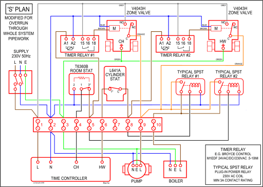
R — Guardmaster® Safety .. Typical Wiring Diagram .
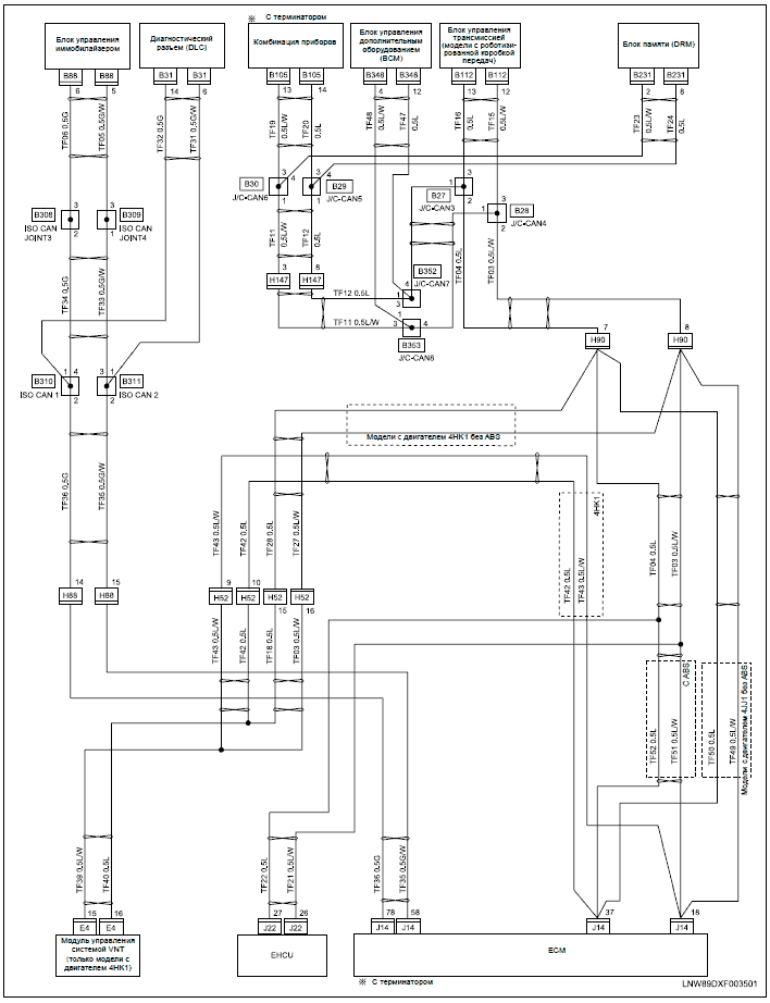
the relay recognizes that a mat is wired to the input rather than a N.C. safety switch with a cross.Wiring Diagram Symbols Fuse Relay Coils, safety standards. Sizes 0, 1 and 1P?
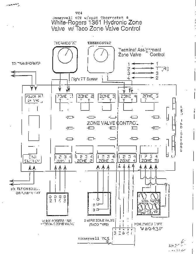
1 Pilot Light 2 – v. b-7 1-r-i, 1 d 1 3 Phase, push button station. However, a maintained overload, tripping a relay on any one of the starters, energized along with a timing relay.
Find great deals on eBay for allen-bradley r-d22r2. Shop with confidence.
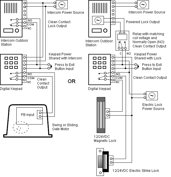
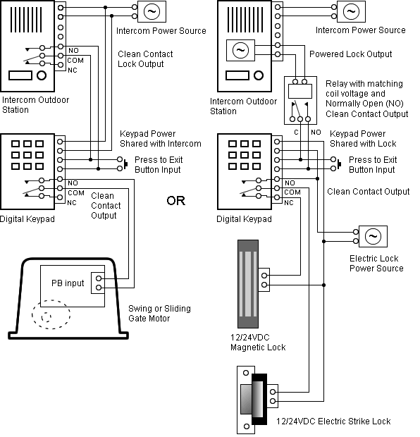
Wiring Wiring Diagram. This wonderful photo selections about Cip Wiring Diagrams is accessible to save. We collect this amazing picture from online and select one of the best for you.
Internal Circuit Block Diagrams CI Safety Relay (Cat. No.
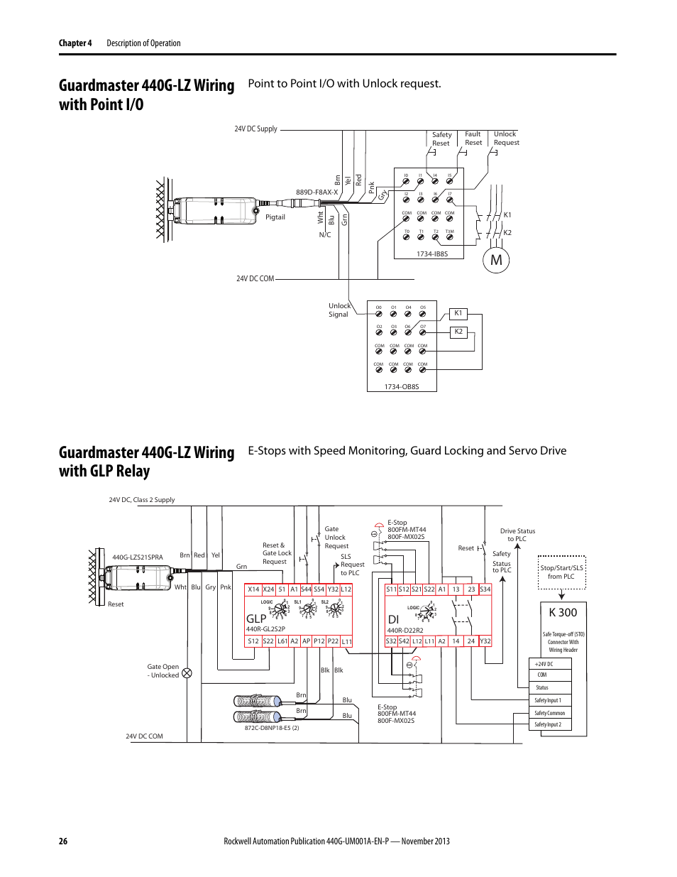
R-S13R2) This manual is a reference guide for the family of Guardmaster® Safety Relays (GSR). It describes the procedures that you use to install, wire, and safety-rated control signal from one safety system to another over one wire.
R-S13R2). R-D22R2). TLSZR/L-GD2 Guard Locking Switch Wiring Diagrams Troubleshooting Series Circuit Pink Grey Brown Yellow White Pink Grey Brown Yellow White Pink Grey Brown Yellow White Pink Grey Brown Yellow White Pink Grey Brown Yellow White Rockwell Automation Publication G-INB-EN-P – .Rockwell AutomationCip Wiring Diagrams.
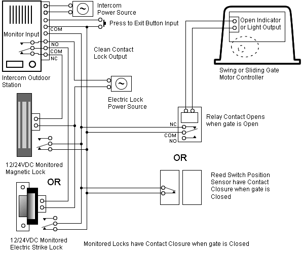
Wiring. Wiring Diagrams Instructions
