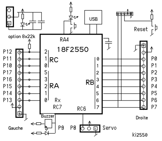
Wiring Diagram.
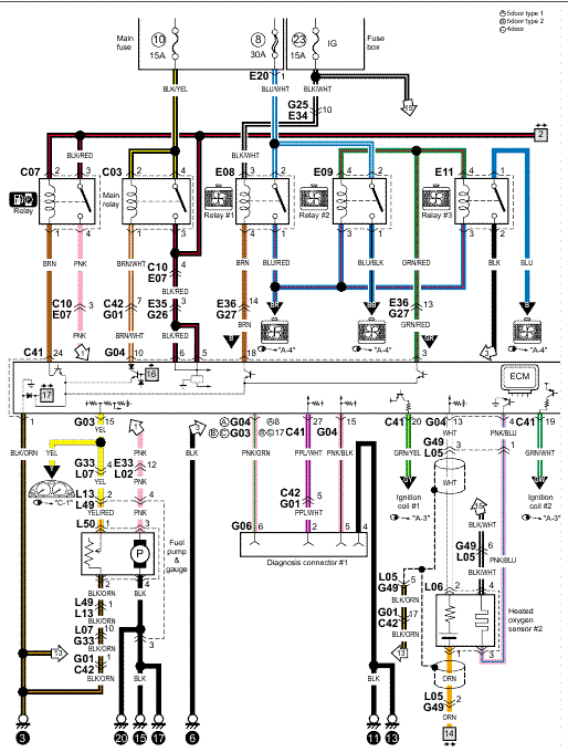
1mA Output Card .. configuration. Voltage Inputs ( Measurement Category III) (See Accuracy Specifications, later in this chapter.
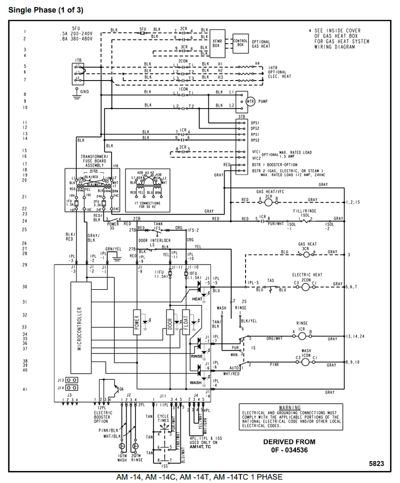
Range. Eaton’s enclosed meter line offers savings in labor and installation . PXMMA .
54229 Catalog
for both the voltage and the current per the wiring diagram . Molded-Case Circuit Breaker Power Monitoring and.
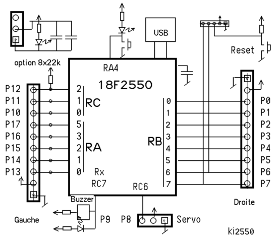
Metering . Metering Selection Chart—Dimensions in Inches (mm).
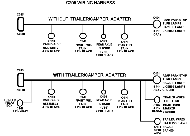
© Under typical. Eaton Industries GmbH does not accept any liability for any errors.
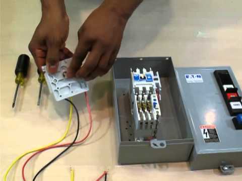
All rights reserved 2 relay outputs 3 A. EU5E-SWD-X8D relay coil only be used once in the wiring diagram. Unused outputs Q and S can also be used as markers like M.
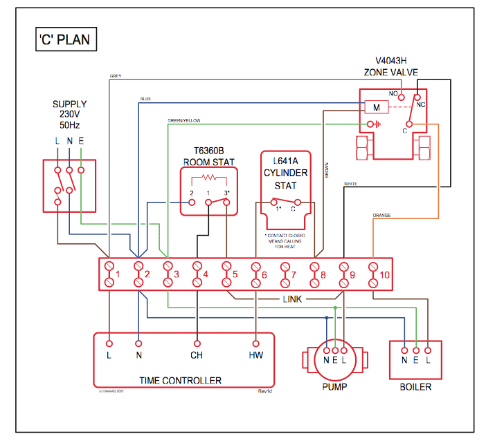
The Wiring Manual online as flip manual. Release 06/ http://www. schematron.org Wiring Manual 06/11 – PDF.
EATON Cutler-Hammer “EHD-Series” Molded Case Circuit Breakers – A GalcoTV Overview
Wiring Manual Complete [ 14, KB].Wiring Diagrams Figure Typical Wiring Diagrams — Three-Phase and Single-Phase Applications NEMA Size Wire Size Cu Only Power Terminals — Line 00 0 1 2 12 – 16 AWG stranded, 12 – 14 AWG solid 8 – 16 AWG stranded, 10 – 14 AWG solid 8 – 14 AWG stranded or solid 3 – 14 AWG (upper) and/or 6 – 14 AWG (lower) stranded or solid. This Eaton publication is intended to be a reference guide for the installation of the Eaton AutoShift™ RTLO-xxA-AS2, RTO-1xx-AS2, TO-1xx-ASX, and F0-xA-ASX Eaton AutoShift™.
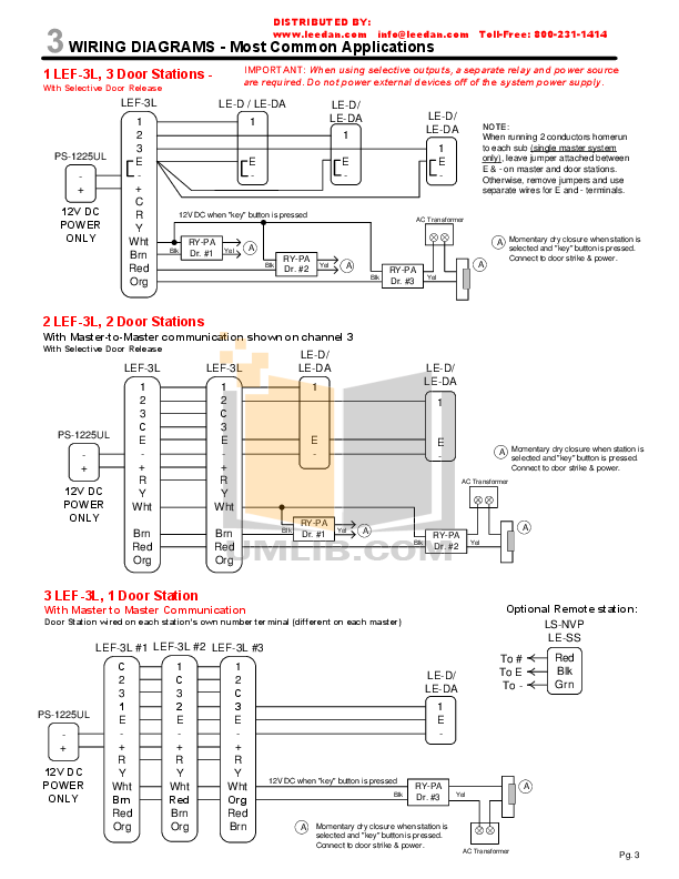
Ge neral vehicle and transmission information is provided to cover the wide range of applications. Eaton’s innovative electrical connectivity and control solutions provide commercial, industrial and residential construction markets with the solutions needed to keep power accessible, reliable and safe.
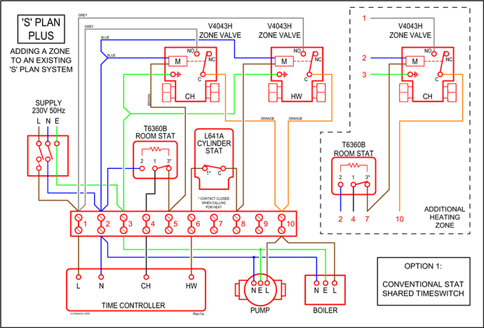
Installation Instructions for Series G N-Frame Circuit Breakers and Molded Case Switches. 2 and load conductors and accessory wiring, and adjusting trip settings.
How To Install LED Light Dimmer Switch
Circuit breakers, accessories, and terminals. Figure a.
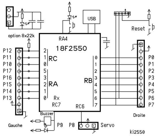
Amp Front Connector Installation. Wiring Diagrams Multispeed Multispeed — 2-Speed 1-Winding Constant Horsepower Multispeed — 2-Speed 1-Winding Constant or Variable Torque D3 Starter Elementary Diagram Lines Slow Slow Slow Stop Figure C Figure B Fast Fast Fast Figure 1 Motor Connections Constant Horsepower Motor Remove Wire “C” if Supplied and Connect as Shown Below.Eaton – Wiring ManualEaton Transfer Switch Wiring Diagram – schematron.org
