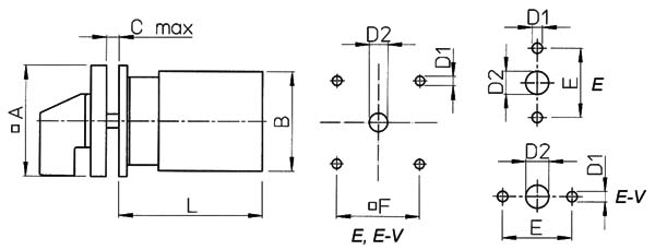
Switch Wiring Diagram App Kraus & Naimer Schaltungsbuch Übersicht mit Schaltplänen Normschaltbilder der C-, CA-, CG und CH- Reihe Hinweise für. CAD..
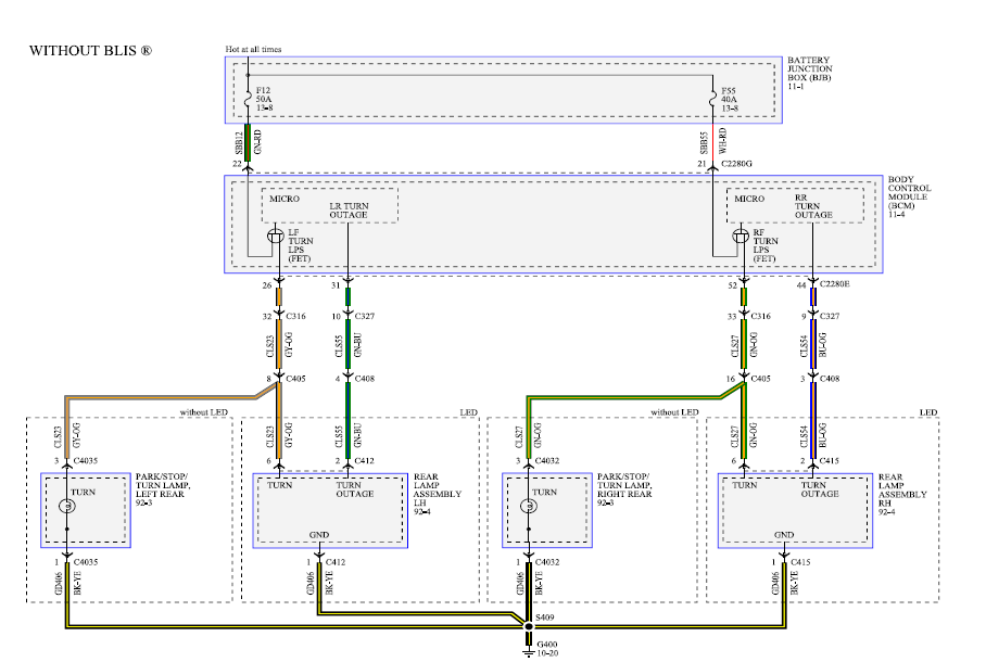
CA CA CA10B- CA CL4. CA25 CA25B C CL Code Stages. Connection Diagram.
A A A A A schematron.org 1. Kraus & Naimer f The full code would now be CA10 A E. The color code is ..
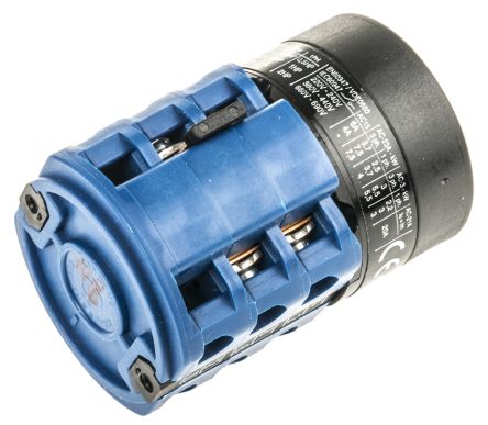
Flexible AWG wires (without sleeve). Ambient.
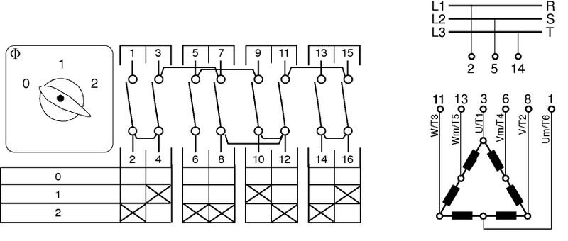
Pole and Throw Configuration SP, Width 48mm, Brand Kraus Naimer, Actuator Type Rotary Knob, Angle of Throw 60°, Maximum Voltage V, Maximum. C-, CA-, CG- and CH-series cam switches.
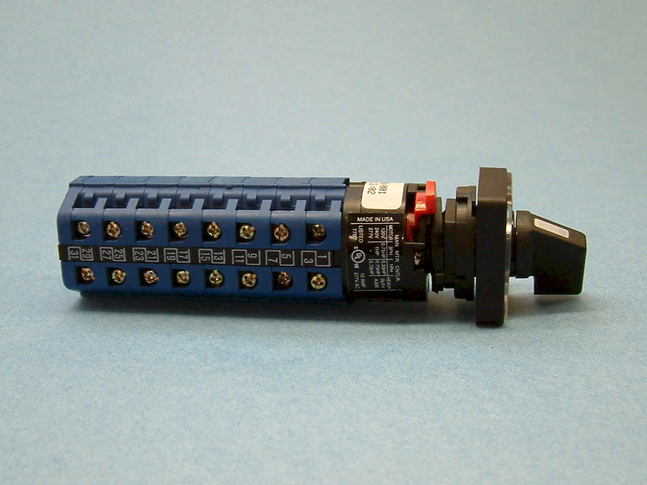
For details on special or non- standard switches, please contact our local sales office. Switch wiring diagrams.KRAUS & NAIMER The development of the Blue Line rotary switch, contactor and motor starter product ranges is based on more than seventy-five years experience by Kraus & Naimer in the design and manufacture of electrical switchgear. According to IEC , EN , VDE part Rated Thermal Current Iu/Ith/Ithe A 20 Rated Insulation Voltage U i 1 V Rated Impulse Withstand Voltage U imp.

– Wiring Diagram kraus naimer ca Abstract: CA10 A kraus and naimer Ca4 kraus naimer ca10 star delta wiring diagram motor start y Wiring Diagram kraus naimer ca20b KRAUS NAIMER CA10 A Ca20b CA20 kraus it naimer kraus and naimer c32 Text: organization. Kraus & Naimer’s highly compact CAD-Type cam switches are used in a wide range of electrical and electronic applications.
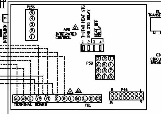
They are particularly suitable for semi-conductor circuits and can be also be used for relay and contactor control. They meet all requirements for controls switches in conventional systems. Wiring Diagram kraus naimer ca10 datasheet, cross reference, circuit and application notes in pdf format.CA10 A PF1 – Kraus & Naimer – – e-catalogCA20 kraus naimer wiring diagram for 2 position t datasheet & applicatoin notes – Datasheet Archive
