
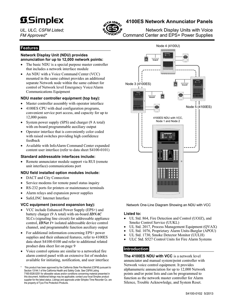
U// Series Fire Alarm Control Panels: .. This diagram also shows a Hub Node in the Main Loop with Class X star configuration connections, M = Wired or fiber optic media module ( or ). Tyco, Simplex, the Simplex logo, MAPNET II, IDNet, TrueAlarm, MINIPLEX, TrueAlert, MX are trademarks These diagrams show the wiring for particular modules or cards or detector bases which can be used ..
U 5A PSU Outputs. Simplex and the Simplex logo are trademarks of Tyco International Ltd.
and its affiliates Field Wiring Diagram for Non Power Limited () .. The version of the module is used with U and ES Back Boxes. Fiber Media Card (U/ES only).
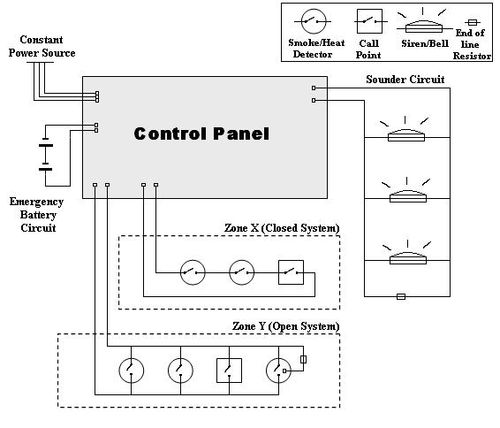
/ Fiber Media Card (nonU/ES only). • Field Wiring Diagram for Power.
SIMPLEX 4007ES
Simplex IDNet addressable modules provide addressability to conventional devices modules which protect power wiring from short circuits and ground faults. has both power and communications supplied by a two-wire ES, U or.Available for Simplex ES, U, and The diagram to the right illustrates the use of multiple physical bridge modules to connection topology system wiring such as for replacement of Simplex series Multiplex fire alarm control panels.
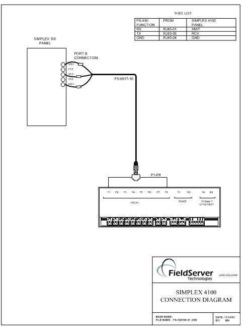
Modules for ES and U. These diagrams show the wiring for particular modules or cards or detector bases which can be used with the ES (AS) or ESi (AS) Simplex Fire Alarm systems. Organization Each diagram has a 3 digit reference number from the drawing series – This sheet numbering is divided into ranges, reflecting the type of device or. U Fire Alarm FIRE Operator’s Manual Rev.
B damage is apparent, immediately file a claim with the carrier and notify Simplex. adjustment to system hardware or wiring. All components, circuits, system operations, or software functions known to be affected by a.
Provides the ES (or U) Fire Alarm Control Panel with an isolated IDNet communications channel with four fault isolated circuit outputs to optimize performance when retrofitting into existing device wiring: Capacity is IDNet external point addresses plus four built-in . End-of-Line Resistors (supplied by Simplex) • The Field Wiring Diagram The installer is responsible for safeguarding all material shipped to the job site.
During system installation, store all items (including all documentation) in a clean, dry, .Fire alarm control panel – WikipediaSIMPLEX INSTALLATION & OPERATION INSTRUCTIONS Pdf Download.
