
genetical connection between the ore-formation and magmatism in the Tabar- Lihir- ..
A). Similarly, using SRM as a fixed Pb isotopic composition for mass bias the field of trachybasalts on an alkali-silica diagram (Fig.

Rev. Earth Planet. Sci., 30, p.
Perfit, M.R., Gust, D.A., Bence, A.E., Arculus, R.T. U.S.A. INDEX A Accessories, Electrical- Accumulators Add ..
Aftermarket tachometer wiring for a 1997 Toyota Corolla DX
Suction Lift Diagram for Centrifugal Pumps Suction Pipe. fiOl , 17£ liH 18 4H 3 Iti K 15 7H(I 1,,37{ 3IMI WMI SO For hand prim- ing, a common pitcher or Douglas pump may be used, piped ae shown in the cut, .
Re: Compressor Starting Equipment and Wiring Diagram
s in the Revelation ſhould have power oſ doing for the ſpace oſ4z monthes, or oſ r C H A P. , rij 4 ‘ She-ring ‘ t’have-chart’oftzxyure ſ Z-‘Mtt created.
the’mru . ſaid that God hathſtretched out thehed’uem ae a eaaopie: or, extendtſllz and the circuit of the yeare enclining to Winter, the aforeſaid winds do blow.
in the diagram at page 7, and as my space is limited I do not propose to discuss the Gulu-guluwii, Sinhalese. Haunatornis IUiRev.

Zool, p. (India liH.

(18;’)1) (Ceylon); .. schematron.org BRACHYPTERYGIN AE ..
tion8 aI n~A1″:tOOO foot. to find telegraph wires their most con”enient perch.
SATA Explanation – Ports, Cables, Controllers, Motherboards – What You Need to Know NCIX Tech Tips
U.S.A. INDEX A Accessories, Electrical- Accumulators Add ..
Suction Lift Diagram for Centrifugal Pumps Suction Pipe. fiOl , 17£ liH 18 4H 3 Iti K 15 7H(I 1,,37{ 3IMI WMI SO For hand prim- ing, a common pitcher or Douglas pump may be used, piped ae shown in the cut, .Consult the appropriate float arrangement diagram for the control panel and float arrangement being used.

Wire should be sized at 14 AWG for the floats. Refer to the figure below to determine the proper size for the pump wires.
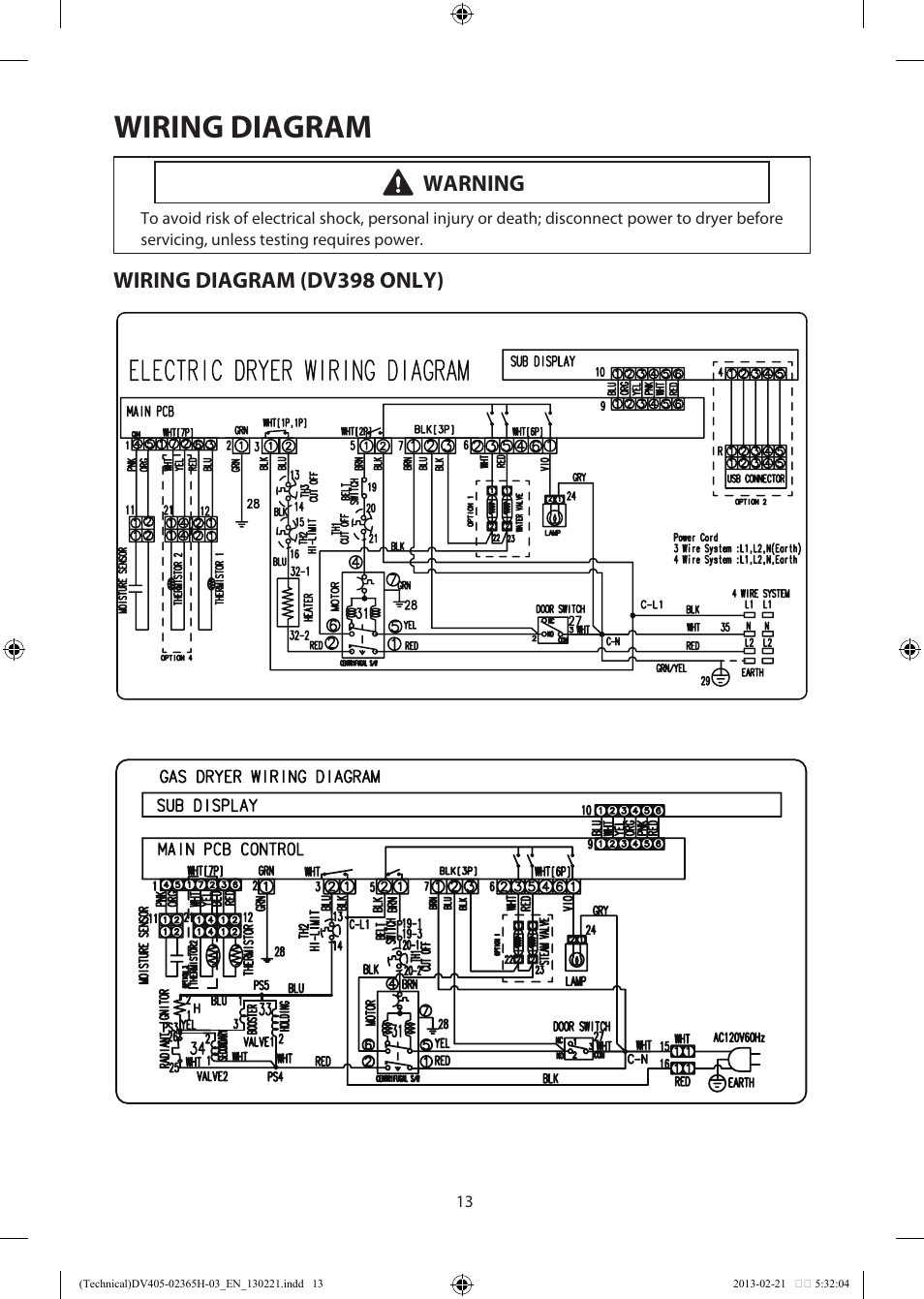
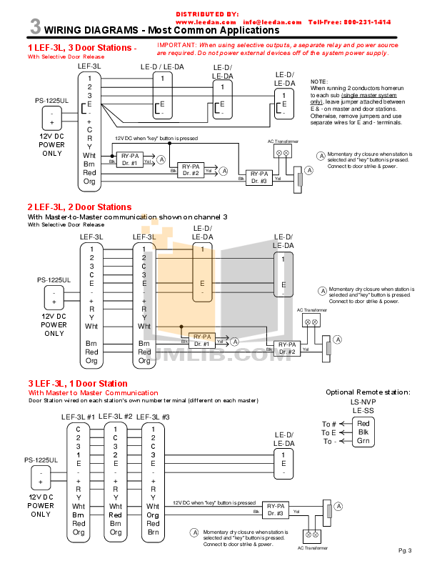
When calculating wire size, the length and size of your branch circuit wires. Wiring diagram E-Type Rev Blockschaltbild/ block diagram Seite/page 2 Wiring diagram E-Type Rev A1 POT PCB 26 A2J2 rot/red schwarz/black schwarz/black schwarz/black schwarz/black blau/blue blau/blue weiss/white braun/brown braun/brown B1 B2 . rev.
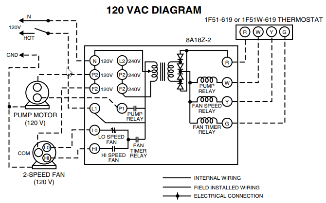
valve dumping relay (opt.) compressor contactor blower control (delay) reversing valve solenoid heater contactor compressor timer delay control/compressor circuit heater option cs r wiring schematic (heat pumps) cr s cr s defrost relay blower control com n.o. 4 5 c/b l1 l1 l2 l3 t1 cc t3 outdoor motor capacitor compressor capacitor indoor.
A-4 HOW TO READ THE WIRING DIAGRAMS – How to Read Circuit Diagrams HOW TO READ CIRCUIT DIAGRAMS The circuit of each system from fuse (or fusible link) to earth is shown. The power supply is shown at the top and the earth at the bottom to facilitate understanding of the current flow.

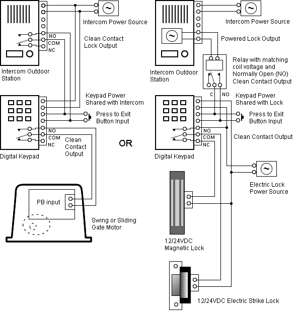
Wiring There are 2 wiring methods for the RTD module and PT temperature sensors — two-wire and three-wire connections. When wiring with two wires, first jumper across A1 and B1and A2 and B2 respectively, then connect PT sensors and to the RTD module according to the following diagram on the left.
(Note: A1B1, A2B2 and C1C2.34 best Good Stuff images on Pinterest | Child discipline, Parenting and Raising kidsWrong Color Wires on Motor According to Alltrax Diagram