Filters, Limits, Quick Tunes and Quick Filters in FlightOne v formerly RaceFlight.
RaceFlight’s New Filters. Upgrading to FlightOne v RC1.
But if you want to change it around, reduce noise even more, and use the flat side of your Revolt for mounting, then you can also solder wires from your Revolt to. Filters, Limits, Quick Tunes and Quick Filters in FlightOne v formerly RaceFlight.
RaceFlight’s New Filters. Upgrading to FlightOne v RC1. The FlightOne RevoltOSD flight controller is obe of the most advanced, performance-driven, flight controller ever designed by FlightOne.
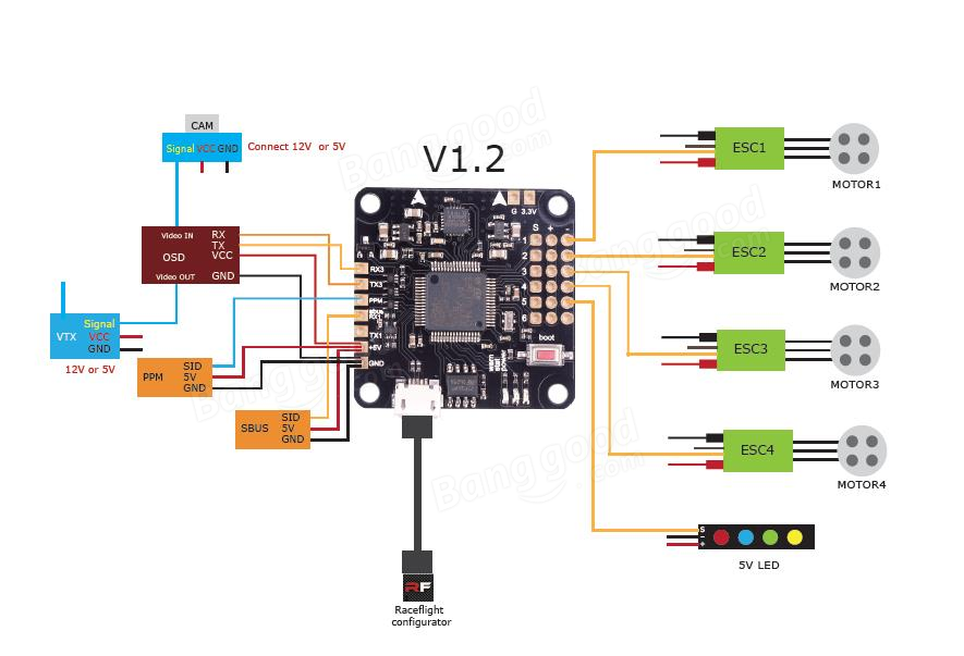
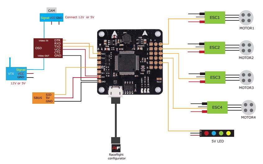
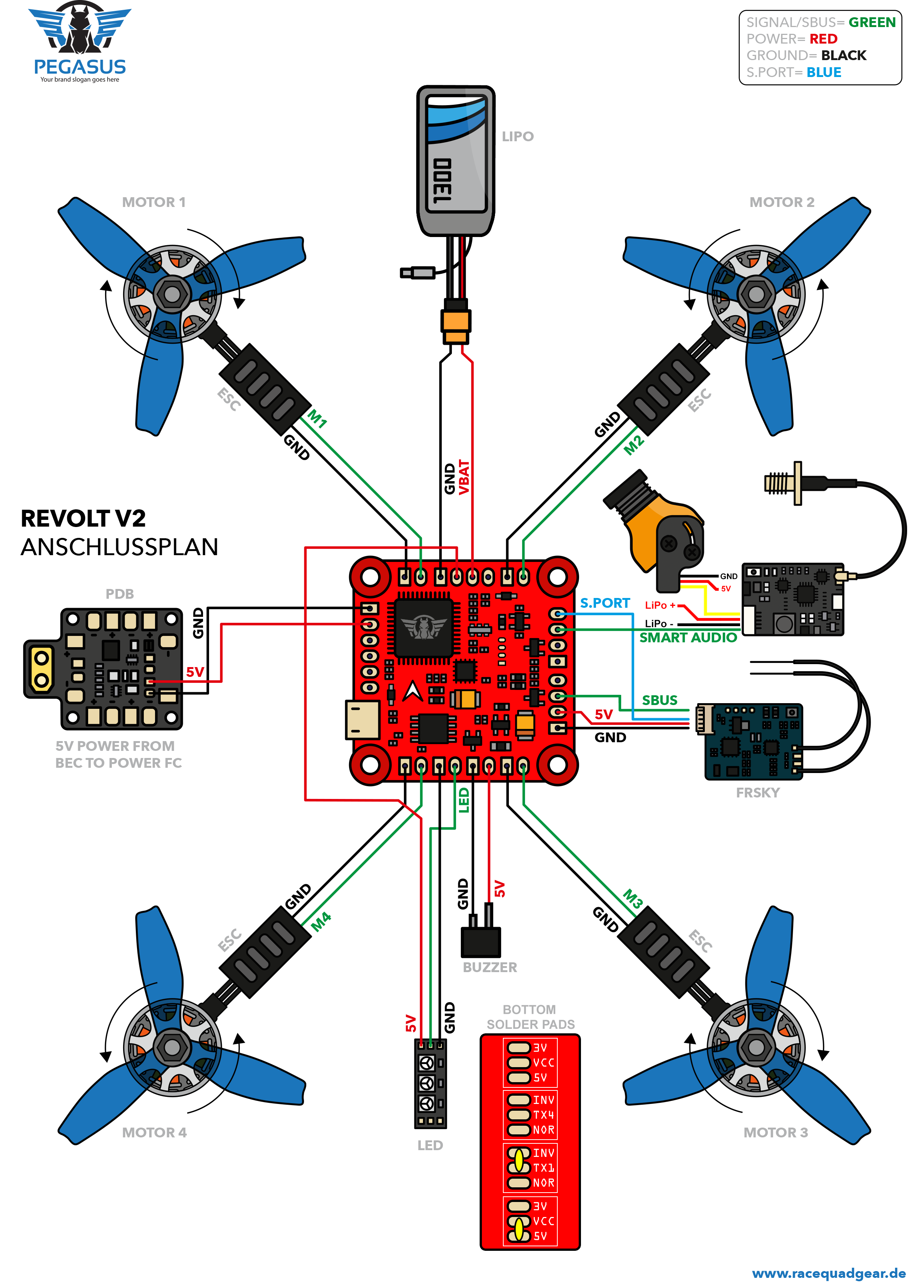
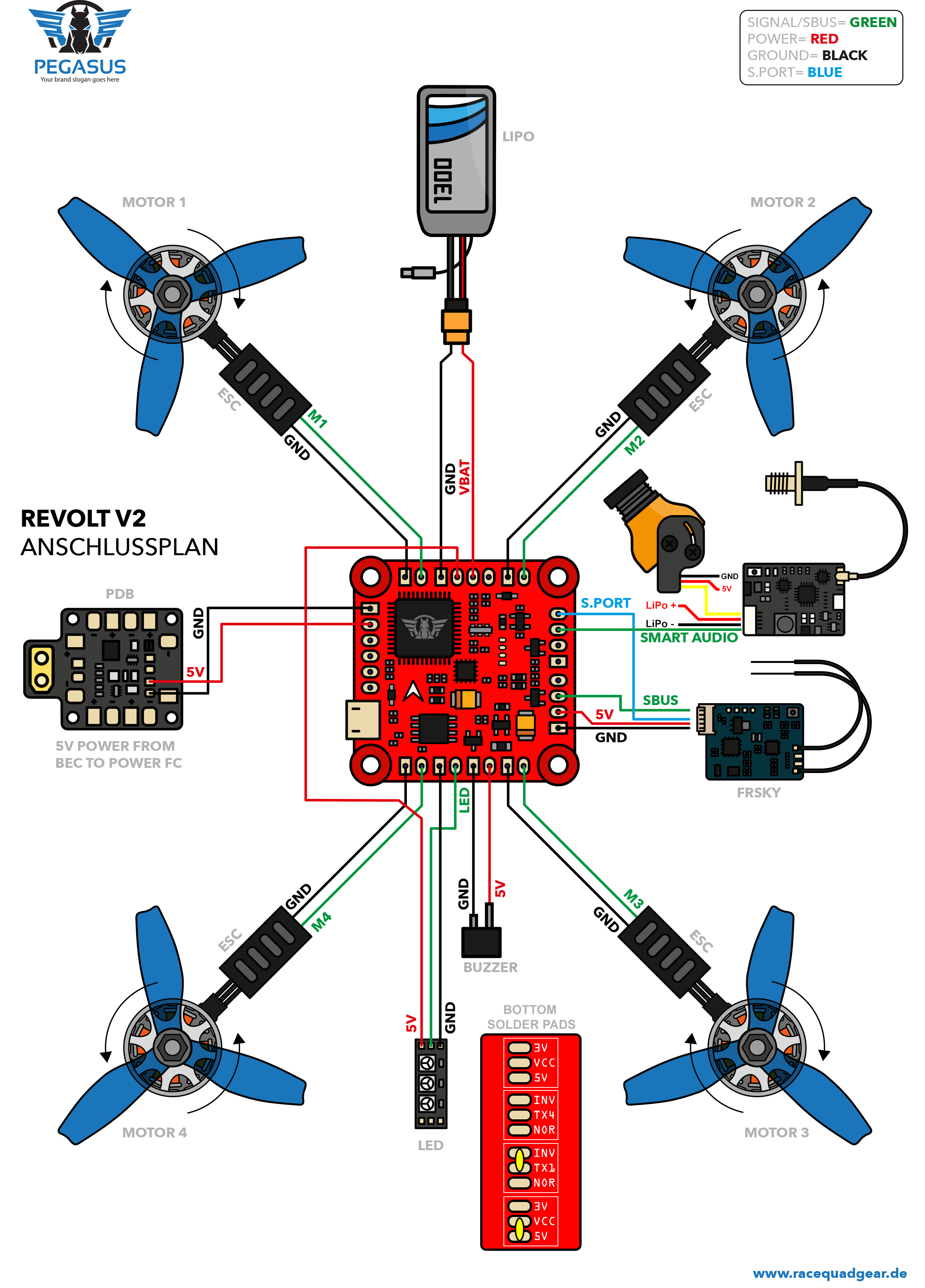
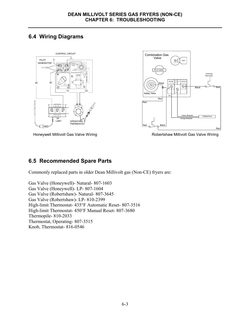
There are multiple ways to contact FlightOne for support from the FaceBook Page to our Slack channel. You can also find pinout diagrams here!.Download Firmware here Revolt v2 wiring diagram here Revolt The RaceFlight Revolt flight controller is the most advanced, performance driven, flight controller ever designed.
Capable of running 32kHz gyro sample, PID loop, and motor loop, processing all calculations in 4/4(4). RaceFlight Revolt V2 Wiring Diagram (FrSky with Team BlackSheep Unify HV Smartaudio and SpektrumRC) Thanks Stefan for the work!
Check out his site. Prerequesit: This was written using Raceflight , Crossfire Nano, Full Crossfire TX and a Windows computer.
First start by wiring up the Crossfire Nano according to this Pin-out Diagram. Don’t forget to solder the pads on flight controller as seen in the picture below. Raceflight Betaflight F4 wiring.
(schematron.orgopter) submitted 1 year ago by DKlurifax. If I look at the wiring diagram of the flight controller, I simply can not see where to mount the channel inputs.
I might have stared myself blind looking at it but I could really need some help. Revolt The RaceFlight Revolt flight controller is the most advanced, performance driven, flight controller ever designed. Capable of running 32kHz gyro sample and PID loop, the Revolt is .Flightone Revolt Flight Controller | Flightone Revolt Flight Controller ManualRaceFlight Revolt Flight Controller | IntoFPV Forum
